This post is part of the Rack box project series.
A 19" rack cabinet filled with electronics and AVR microcontroller modules — I called it: The rack box project!
Table of contents
Details
When I was young and single I had a lot of spare time. I lived in a tiny apartment and wanted to build electronic modules for home-automation — and whatever really. I just wanted to solder and make circuit boards. So I got myself a server rack cabinet, and started making electronics and microcontroller modules to fill it with.
Pretty much all electronics I built between 2005 and 2010 went into the rack box project. A lot of it was just to supply and monitor voltage levels, temperatures, fuses, alarms, etc, inside the rack box itself. But it also included a fair amount of home-automation stuff; things like lights and heat control, security alarm system, etc.
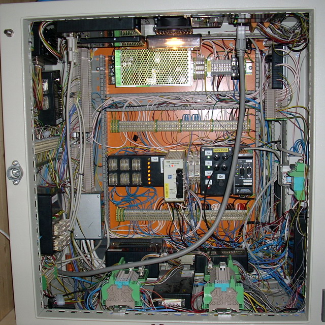
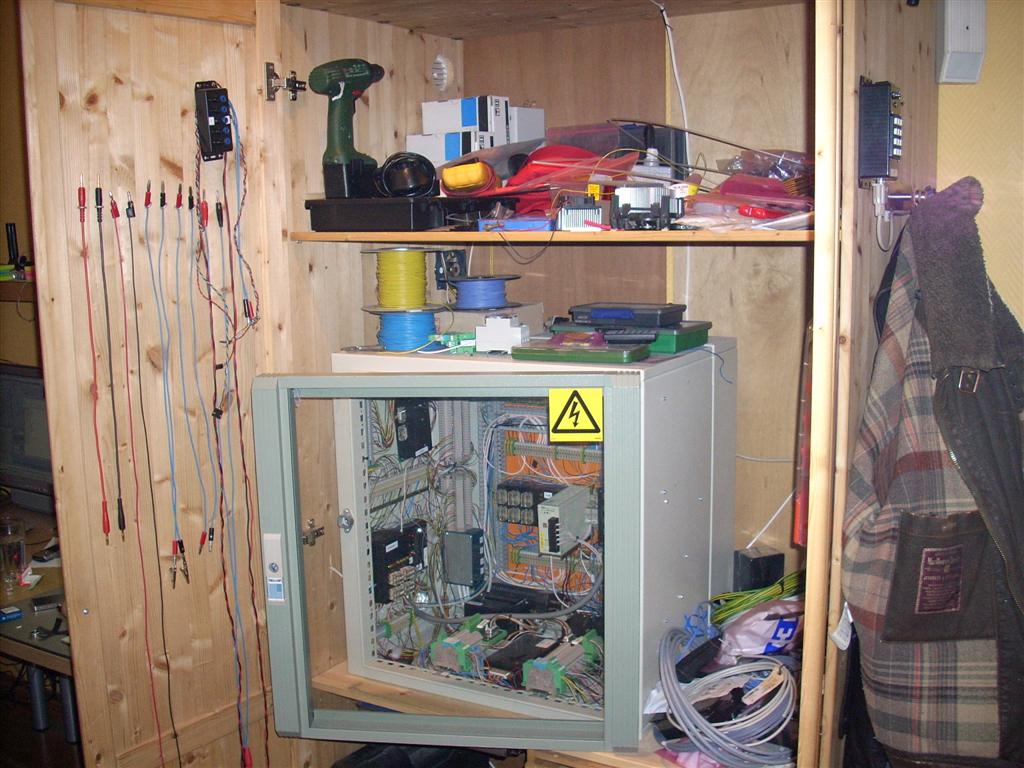
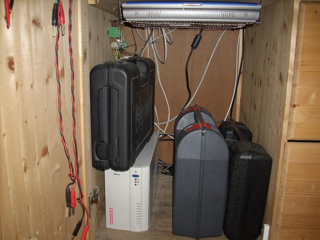
It was a 19" standard server rack cabinet, constructed in steel. Supplied with 230V to four power supplies inside, providing 5, 12, 13.8 and 24 volts. Just “idling” the system used about 13 watts. Power was supplied from a UPS, so it would stay powered on in the case of a blackout.
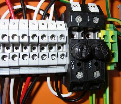
All fuses, power supplies and modules were monitored and trigger an alarm if anything failed. A lot of the modules inside were used for this purpose only. This was partly why I built the thing in the first place — I wanted something to monitor 😃
The rack box connected to the outside world through four D-sub connectors, but it also had RS232 serial cables going to my computer. See the serial I/O system post for more information.
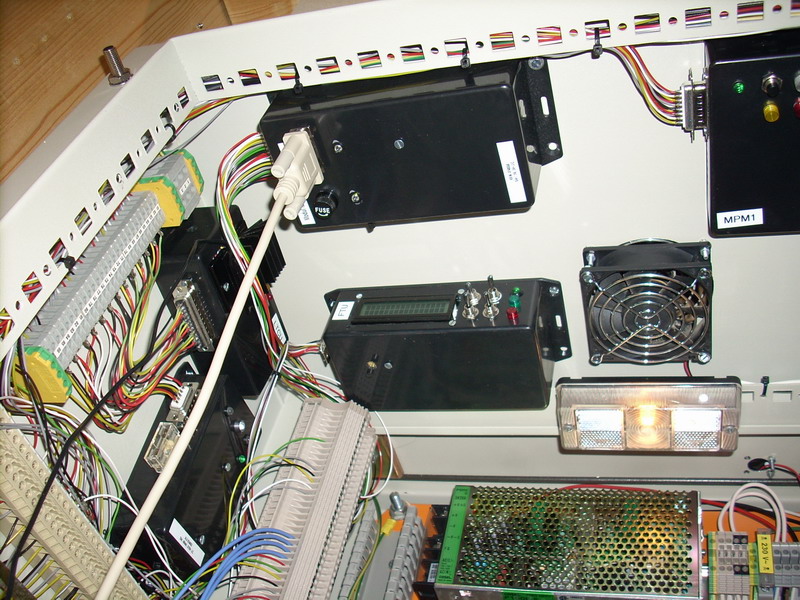
Since it didn’t have any airflow, and a lot of electronics inside got warm, I built a fan and temperature controller to monitor the temperature. It would start a fan if it got hot, and trigger the alarm if it got even hotter.
In case something really bad happened the system also had an emergency shutdown function, that cut the main 230V supply to the system. It could be triggered automatically, from inside the rack box, or on the status panel.
I had a lot of ideas for automatic shutdown in the case of fire or extreme heat, but I never got around to it. The emergency shutdown controller had its own isolated power supply, directly powered by the UPS.
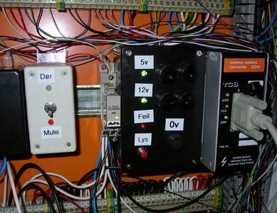
All alarm situations was shown on a stack light, flashing in different patterns, and an audible alarm was sounded. The sound could be pretty annoying, especially at night. So the system had a mute function, which turned off all audible alarms. This was automatically enabled at night with a timer.
Since the whole system was connected to a UPS, it didn’t notice 230V mains failures. For that purpose I had a relay powered by an AC adapter bypassed the UPS. Using that relay the system was able to detect if it was running on battery (the UPS) or the 230V mains.
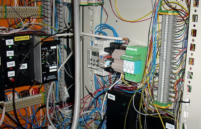
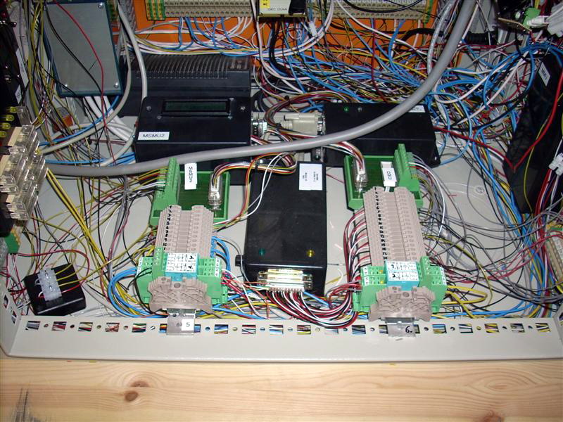
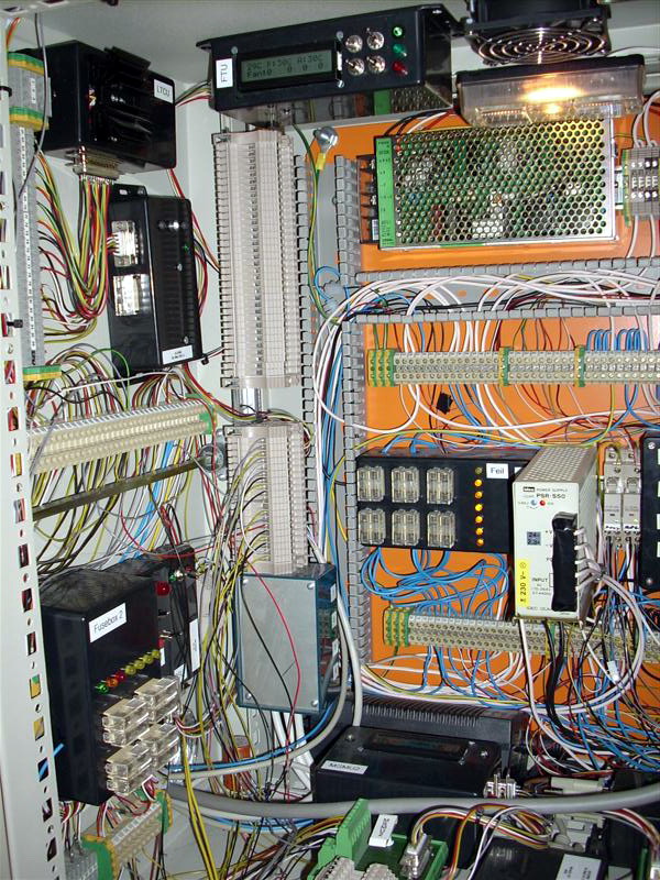
At the end, as the images show, the rack box got really crowded. So I eventually began making stand-alone modules what could be placed outside the cabinet with their own AC adapters and voltage regulators. They still had control cables, connecting them to the rest of the system.
The project ended when I moved out of the apartment in 2010, I removed all modules and electronics and got rid of the rack cabinet. I still have most of the modules, and are rebuilding and reprogramming some of them for other purposes.
Videos
This video shows some of the basic functions of my rack box project.
This shows the fan and temperature-, emergency off- and stability modules.
Power
The rack box alone without any active alarms, lights etc, had a power consumption of about 13 watts. When the stack lights or the interior light was on; the power consumption increased to about 20 watts. The system was protected with a net filter and a UPS.
Supplies
- 5V - 20 amps
- electronics, AVRs, LED lights, etc
- 12V - 2.5 amps
- emergency supply Emergency shutdown unit and Digital emergency interface module
- 13.8V - 4.5 amps
- lights, relays, electronics, etc
- 24V - 2.3 amps
- relays, warning lights
An external 12V power supply was used for detecting mains power loss, meaning that the system was running on battery backup (UPS).
Status panel
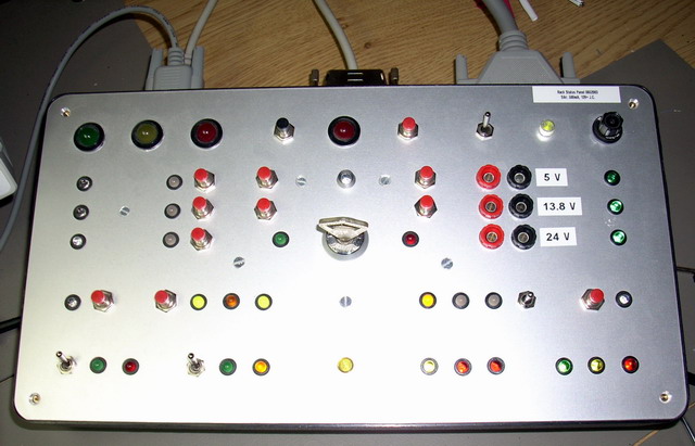
The status panel had LEDs for pretty much every situation that could occur in the rack box. Lights, alarms, fan, mute etc. could also be controlled from the panel.
Emergency shutdown could both be triggered and reset from the status panel.
It was housed in a desk enclosure with an aluminum front plate, this was stiff and did not bend when buttons were pushed.
The panel was connected to the rack box with three D-sub connectors, 9, 25 and 37 pins. If any of the cables were disconnected, or the panel lost contact with the system in any way; an alarm was triggered.
A digital interface module for the emergency shutdown was installed inside the status panel and connected to my computer using a DB9 serial cable.
All voltages (5, 13.8 and 24) was available through lab plugs, and could be activated with a toggle switch. I used it as a “bench power supply”.
My home security system could be activated and deactivated using the key switch. When the alarm, or away mode, was active; all LEDs were turned off and none of the buttons worked.
Modules
- Alarm unit
- Advanced serial interface module
- Digital emergency interface module
- Emergency shutdown unit
- Fan and temperature unit
- Fuse box 1
- Fuse box 2
- Light control unit
- Signal and lights controlling unit
- Mute and illumination controlling unit
- Main monitoring unit
- Multi-purpose module 1
- Module stability monitoring unit 1
- Module stability monitoring unit 2
- Online monitoring unit 2
- Online serial interface device
- Oven and signal unit
- Parallel I/O module
- Sound signal unit
Last commit 2024-11-11, with message: Add lots of tags to posts.
All posts in Rack box project series
- Parallel port I/O module
- Power supply and fuse monitoring module, AVR
- Monitored fuse box, 6 channels
- Stack lights and horn controller — with AVR
- Mute and light controller for the Rack box — AVR module
- Monitored fuse box, 4 channels
- Module heartbeat monitor, 6 inputs — AVR
- Controller for lights and relays — AVR driven
- Emergency power off controller — controlled by 555 timers
- Fan controller with LCD — AVR powered
- Sound alarm control unit — AVR module
- Multiplexer output extender
- Multi-purpose AVR module
- Electric heater and timer controller — AVR
- Module heartbeat monitor, 15 inputs — LCD and AVR
- Serial port I/O module with 11 inputs — AVR
- Serial port I/O module with 9 in and outputs — AVR
- Serial interface for emergency power off — AVR
- Status panel for the Rack box project
- Intruder alarm system controller — AVR
- Serial port I/O module with 15 inputs — AVR
- Serial interface module, with analog and digital I/O — AVR
- The rack box project — an overview