This post is part of the Rack box project series.
Detects and alerts if any of the monitored modules goes silent; meaning their heartbeat stops. Uses an AVR ATtiny2313 microcontroller.
Table of contents
Details
When my rack box project started filling up with modules, I needed (or rather wanted) a way to monitor that they were running and doing what they were suppose to. I tried monitoring the fuses, with this and this, but that just wasn’t practical. I needed a way to know that the modules were not only powered, but running. This module does just that.
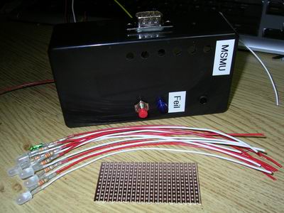
I originally designed all of my devices with a run/life light, an LED that blinked when the firmware was running. This LED was in essence a heartbeat, and by making sure that the heartbeat didn’t stop I would know that the module was working fine.
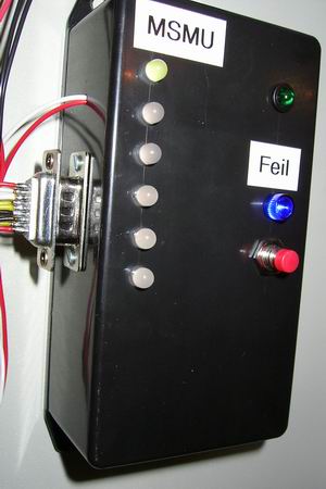
If more than 10 seconds passed, without receiving a heartbeat this monitor unit would go into alarm state. The blue LED would flash, and the green LED corresponding to the failed module would stay solid.
All alarms had to be manually reset, even if the heartbeat came back. The reason for this was so that I would see it if a module had been dead for some time, but came back by itself. This would still indicate a problem with that module. If a heartbeat was not detected at all after a reset, that input was marked as inactive and would not produce any alarms.
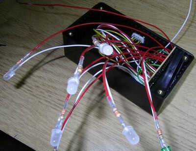
During normal operation the green LEDs flashed every time a heartbeat was received on that input, so it was quite the light show 🙂
Video
The module heartbeat monitor appears at 1:35 in the project rack video. When a fuse is removed; one module stops responding and the monitoring module triggers an alarm. The fuse is put back and the alarm manually reset.
I/O
Inputs
- Module 1 heartbeat
- Module 2 heartbeat
- Module 3 heartbeat
- Module 4 heartbeat
- Module 5 heartbeat
- Module 6 heartbeat
- Reset
Outputs
- Module 1 failure LED
- Module 2 failure LED
- Module 3 failure LED
- Module 4 failure LED
- Module 5 failure LED
- Module 6 failure LED
- Module error alarm
- Life-light
D-Sub 9-pin
- 5V
- 0v
- Module 1 heartbeat input
- Module 2 heartbeat input
- Module 3 heartbeat input
- Module 4 heartbeat input
- Module 5 heartbeat input
- Module 6 heartbeat input
- Reset alarm input
- Module error alarm output
Source code
- Bascom-AVR source is available in a git repository:
- https://github.com/thomasjsn/AVR-Module-heartbeat-monitor
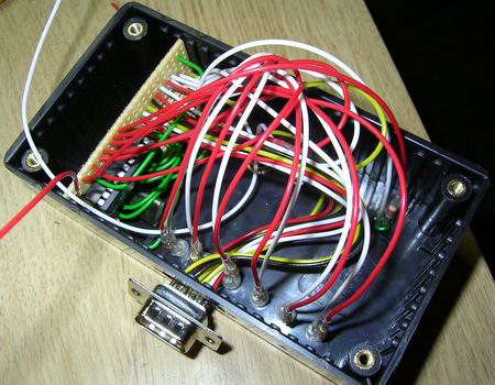
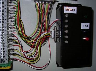
Photos
Parts list
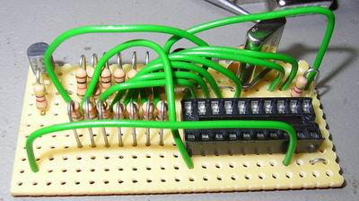
- 1 × AVR ATtiny2313-20PU, DIL-20, 20 MHz, 18 I/Os
- 1 × Capacitor, aluminium electrolytic, 10 µF, 25V
- 2 × Capacitor, ceramic, 22 pF, 100V
- 1 × Capacitor, ceramic, 1 nF, 100V
- 1 × D-sub soldering cups, 9 pin male
- 1 × DIL socket, 20-pin, 7.62mm
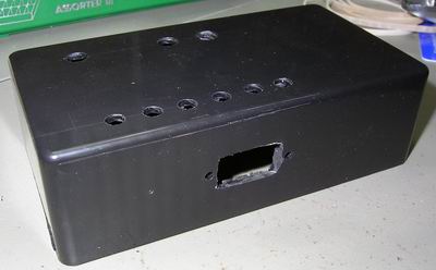
- 1 × Enclosure, plastic (1591 FL), 120x65x40mm, flange
- 1 × LED 5mm clear, Blue, 4.9V, 20mA, 350mcd, 12°
- 1 × LED 5mm coloured clear, Green, 2.1V, 20mA, 30mcd, 10°
- 6 × LED 5mm, Red/Green, 2.0 2.1V, 10mA, 100 63mcd, 30°
- 1 × LED holder 5mm, RTC51, black plastic
- 1 × LED lens 5mm, CLF 280, Blue
- 32 cm2 PCB, stripboard, 100x160mm, 160cm2
- 1 × Quartz crystal oscillator, 4 MHz
- 15 × Resistor, carbon film, 0.25W, 330 Ω, 5%
- 2 × Resistor, carbon film, 0.25W, 4.7 kΩ, 5%
- 7 × Resistor, carbon film, 0.25W, 10 kΩ, 5%
- 1 × Switch, push-button, 1-pole, 1A, 50VAC, off-(on)
- 1 × Transistor, NPN, 100 mA, 45V, 0.5W, BC547B
Last commit 2024-11-11, with message: Add lots of tags to posts.
All posts in Rack box project series
- Parallel port I/O module
- Power supply and fuse monitoring module, AVR
- Monitored fuse box, 6 channels
- Stack lights and horn controller — with AVR
- Mute and light controller for the Rack box — AVR module
- Monitored fuse box, 4 channels
- Module heartbeat monitor, 6 inputs — AVR
- Controller for lights and relays — AVR driven
- Emergency power off controller — controlled by 555 timers
- Fan controller with LCD — AVR powered
- Sound alarm control unit — AVR module
- Multiplexer output extender
- Multi-purpose AVR module
- Electric heater and timer controller — AVR
- Module heartbeat monitor, 15 inputs — LCD and AVR
- Serial port I/O module with 11 inputs — AVR
- Serial port I/O module with 9 in and outputs — AVR
- Serial interface for emergency power off — AVR
- Status panel for the Rack box project
- Intruder alarm system controller — AVR
- Serial port I/O module with 15 inputs — AVR
- Serial interface module, with analog and digital I/O — AVR
- The rack box project — an overview