This post is part of the Rack box project series.
Simple monitoring module for the essentials in the rack box project; power supplies, fuses and communication. Uses an AVR AT90S2313 microcontroller.
Table of contents
Details
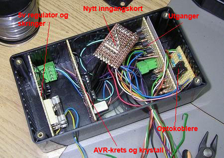
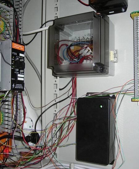
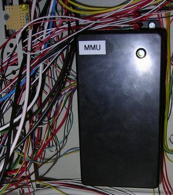
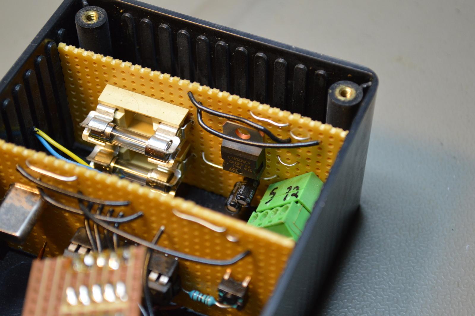
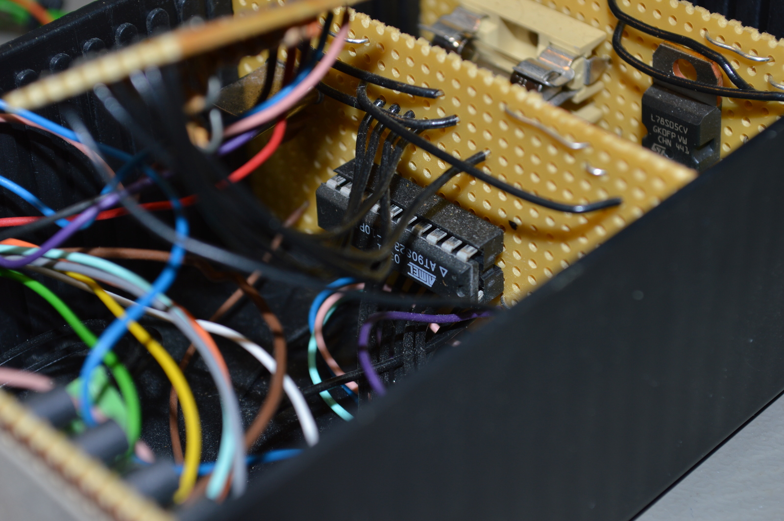
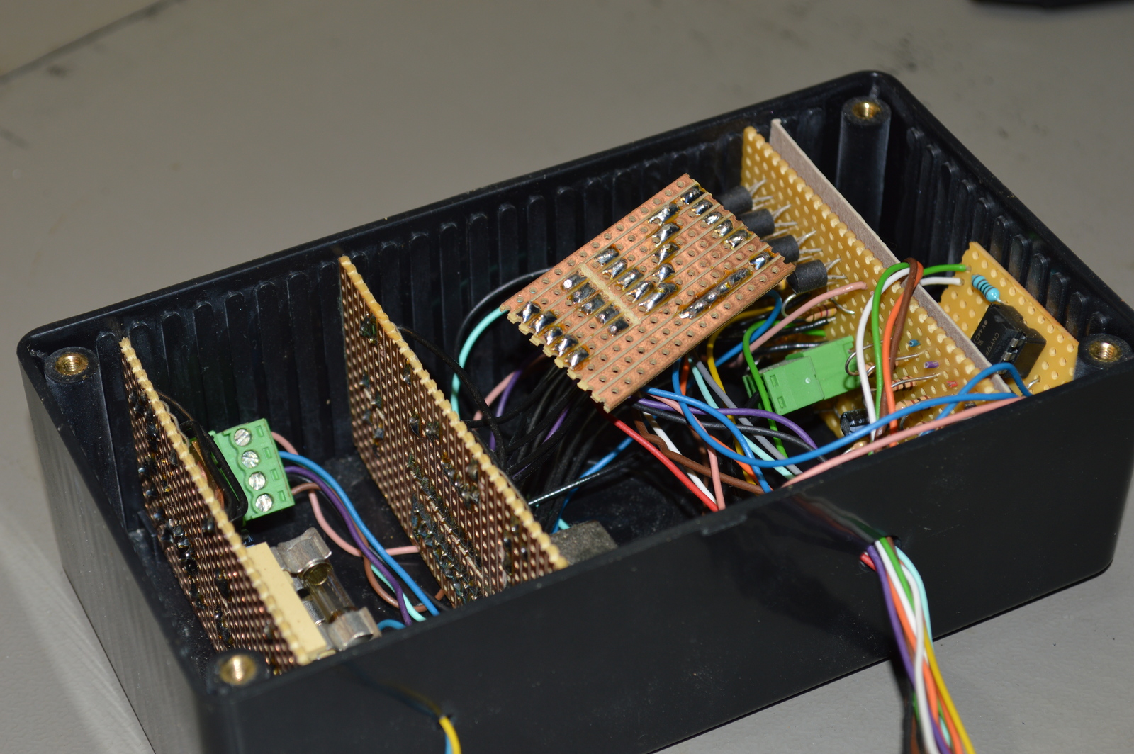
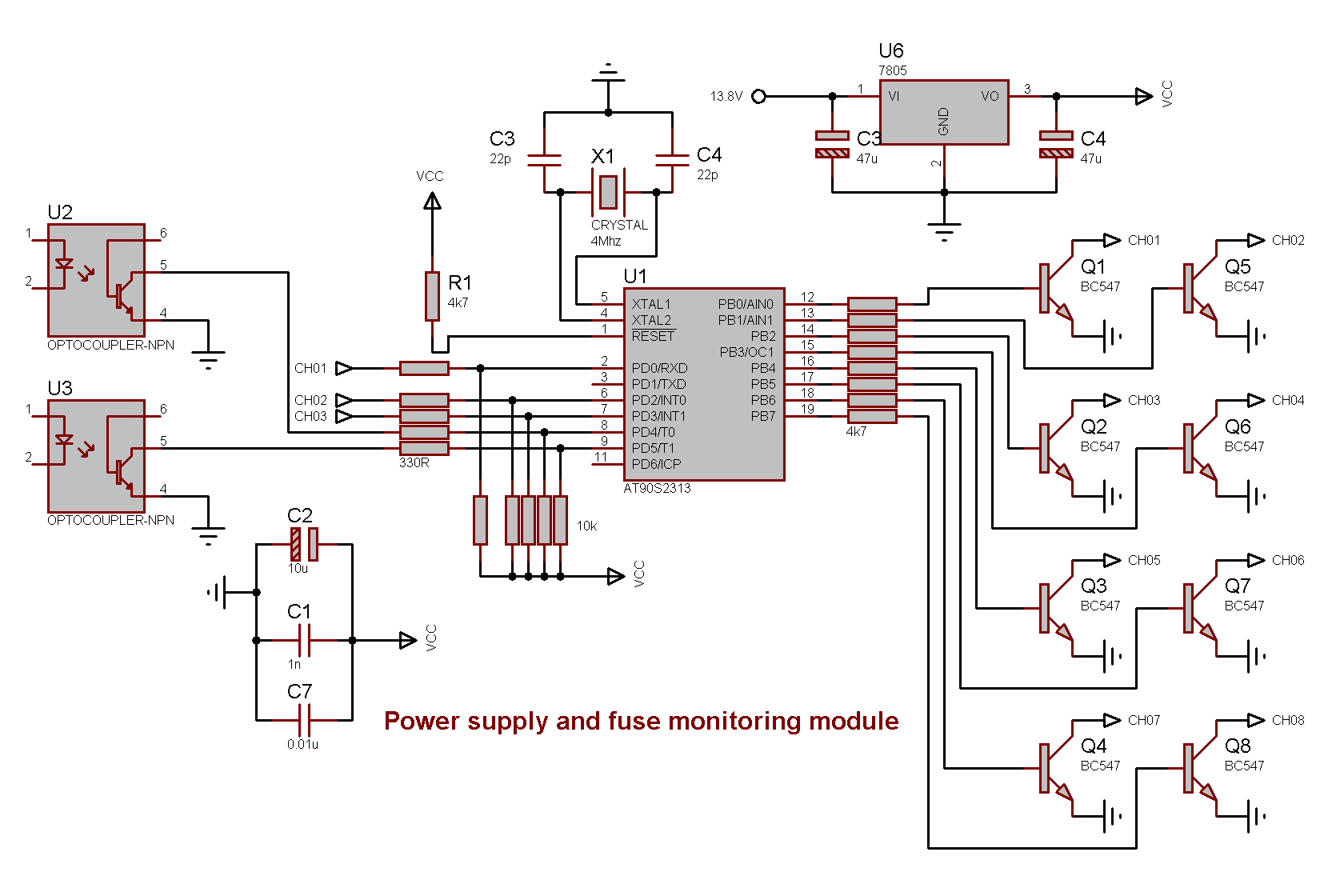
This was the first AVR microcontroller module I ever built, it was made for, and installed in the rack box project. As the name suggests it monitored that the essentials were OK, that means power supplies, fuses and communication. It used optocouplers to detect if the 5 or 12 V power supply failed, but depended on other modules for the fuse, emergency supply and communication failure.
When a situation were detected the corresponding LED would flash, and there was a sound signal. These LED outputs were later also used to notify other modules, like the controller for the stack lights and the sound signals. So it was a daisy chain of connected inputs and outputs.
One problem with monitoring the 12 V power supply was that this module needed 12 V to work… So it bypassed the 12 V main fuses, but if that supply failed completely the monitoring module would also fail. And thus no alarms, it wasn’t really a bullet-proof solution 😛
Alarm situations
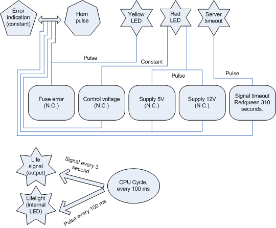
Server timeout
To make sure my Linux server was present, responding and the I/O module was OK; a heartbeat signal was sent every 60 seconds. If this signal went silent for over 310 seconds, meaning 5 minutes and a bit, the server was regarded as timed-out and the alarm triggered.
Emergency supply failure
Without the emergency supply voltage the emergency stop would not work, so that was important. A N.C relay was connected to this supply, and if the supply dropped the relay would activate the emergency failure input.
Power supply failure
The 5 and 12 V supply were monitored with internal optocouplers, so if any voltage or polarity was dropped; it was detected by the module. When a 24 V power supply was added later; an additional optocoupler was installed between 5 V ground and the monitoring module input.
Fuse error
The detecting of broken fuses happened in the fuse boxes (this and this), they sent a signal when a fuse broke which caused this module to sound the alarm.
Try and try again
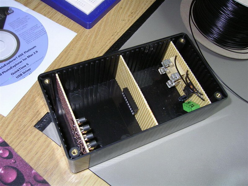
This being the my very first AVR microcontroller project, it took a bit of time to get it to work and I made some schematic mistakes. That’s why you can see a few extra strip boards stuffed into the box in the images, I used the wrong resistor values for all the inputs and had to redo those. That was also when I added the optocouplers.
Thoughts
In retrospect I don’t think the module was very useful, but it was a fun learning experience back then. If a main power supply fails, it is going to have a big impact. Like if the 5 V supply failed, all microcontrollers would stop. Meaning no controller would be alive to receive the error signal.
If the 12 or 24 V supply dies there would be no horn, sirens or lights to show the error. So it seems that the best option for a monitoring module like this would have been to have been completely self sufficient, own warning lights, horns etc. And a battery failover. Maybe next time 🙂
I/O
Inputs
- Server heartbeat
- Fuse error (N.O)
- Emergency supply failure (see Emergency shutdown unit) (N.O)
- 5V supply (N.C)
- 12V supply (N.C)
Outputs
- Buzzer (not in use)
- Error signal (to Signal and lights controlling unit)
- Fuse error LED
- Supply failure LED
- Life-light (built-in LED)
- Life-signal to Module heartbeat monitor
- Server timeout LED
Wires
- Yellow 12V+
- Blue 0V
- Black Server life-signal (in)
- Red Fuse error (in)
- Purple Emergency supply failure (in)
- Green 5V+ supply (to opto-isolator)
- White 5V- supply (to opto-isolator)
- Orange 12V+ supply (to opto-isolator)
- Brown 12V- supply (to opto-isolator)
- Green Buzzer (out)
- Yellow Error signal (out)
- Orange Fuse error (out)
- Grey Supply failure (out)
- Brown Life-signal (out)
- Cyan Server timeout (out)
Source code
- Bascom-AVR source is available in a git repository:
- https://github.com/thomasjsn/AVR-Power-supply-fuse-monitor
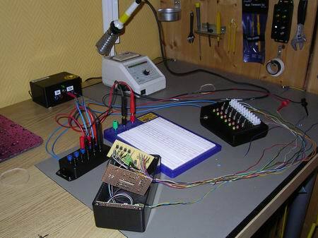
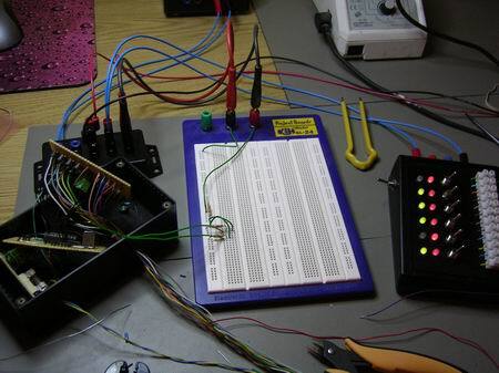
Photos

Schematic drawing
Parts list
- 1 × AVR AT90S2313-10PI, DIL-20, 10 MHz, 15 I/Os
- 1 × Capacitor, aluminium electrolytic, 10 µF, 25V
- 2 × Capacitor, aluminium electrolytic, 22 µF, 25V
- 2 × Capacitor, ceramic, 22 pF, 100V
- 1 × DIL socket, 20-pin, 7.62mm
- 2 × DIL socket, 6-pin, 7.62mm
- 1 × Enclosure, plastic (1591 FL), 150x80x50mm, flange
- 2 × Fuse 5x20 mm, 400 mA, fast-acting
- 2 × Fuse holder, open, PCB, 5x20mm
- 1 × LED 5mm coloured clear, Green, 2.1V, 20mA, 30mcd, 10°
- 1 × LED holder 5mm, RNG 268, Fixing ring
- 2 × Optocoupler, single, CNY17F-3, DIL-6
- 128 cm2 PCB, stripboard, 100x160mm, 160cm2
- 1 × Quartz crystal oscillator, 4 MHz
- 5 × Resistor, carbon film, 0.25W, 330 Ω, 5%
- 9 × Resistor, carbon film, 0.25W, 4.7 kΩ, 5%
- 5 × Resistor, carbon film, 0.25W, 10 kΩ, 5%
- 3 × Resistor, metal film, 0.6W, 1 kΩ, 1%
- 1 × Switch, push-button, PCB, 1-pole, H4.3mm, vertical, black
- 1 × Terminal block, pluggable, 3.5 mm, 2-pin screw female
- 1 × Terminal block, pluggable, 3.5 mm, 2-pin vertical male
- 1 × Terminal block, pluggable, 3.5 mm, 4-pin screw female
- 1 × Terminal block, pluggable, 3.5 mm, 4-pin vertical male
- 8 × Transistor, NPN, 100 mA, 45V, 0.5W, BC547B
- 1 × Voltage regulator +5V, 2 A, L78S05CV
Last commit 2024-11-11, with message: Add lots of tags to posts.
All posts in Rack box project series
- Parallel port I/O module
- Power supply and fuse monitoring module, AVR
- Monitored fuse box, 6 channels
- Stack lights and horn controller — with AVR
- Mute and light controller for the Rack box — AVR module
- Monitored fuse box, 4 channels
- Module heartbeat monitor, 6 inputs — AVR
- Controller for lights and relays — AVR driven
- Emergency power off controller — controlled by 555 timers
- Fan controller with LCD — AVR powered
- Sound alarm control unit — AVR module
- Multiplexer output extender
- Multi-purpose AVR module
- Electric heater and timer controller — AVR
- Module heartbeat monitor, 15 inputs — LCD and AVR
- Serial port I/O module with 11 inputs — AVR
- Serial port I/O module with 9 in and outputs — AVR
- Serial interface for emergency power off — AVR
- Status panel for the Rack box project
- Intruder alarm system controller — AVR
- Serial port I/O module with 15 inputs — AVR
- Serial interface module, with analog and digital I/O — AVR
- The rack box project — an overview