This post is part of the Rack box project series.
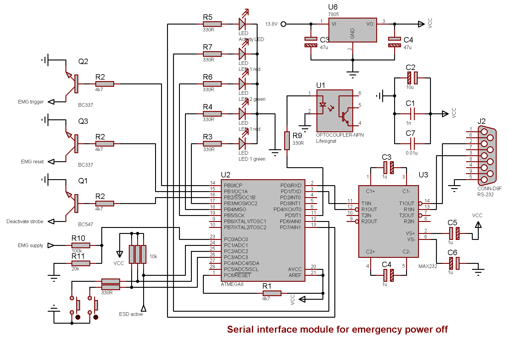
RS-232 interface module, with voltage measurement. Used to communicate with the emergency power off unit in the Rack box project. Installed inside Rack box status panel. Uses an AVR ATmega8 microcontroller.
Table of contents
Details
With this interface it’s possible to trigger and reset the emergency power off from Serial Client. The voltage on the 12V emergency supply is also measured and shown in Serial Client.
The module also registers if the emergency power off is triggered and gives the option of disabling the emergency strobe.
It has three LEDs and one two-way switch on the Rack box status panel, a yellow LED flashes when there is serial activity.
Two LEDs are dual colored (green/red), the color can be controlled from the computer. The switch can be set up using triggers in Serial Server.
Commands
Inputs
- Value from emergency supply 12V
- Emergency shutdown status
- Status on switch 1
- Status on switch 2
Outputs
- Trigger emergency shutdown (1 sec pulse)
- Reset emergency shutdown (10 sec pulse)
- Deactivate strobe (on/off)
- LED 1
- 0: Off
- 1: Green
- 2: Red
- LED 2
- 0: Off
- 1: Green
- 2: Red
I/O
Inputs
- PC0 - Emergency supply 12V voltage for volt meter
- PC1 - Emergency shutdown active (Emergency power off unit)
- PC2 - Switch 1
- PC3 - Switch 2
Calculations
Voltage
(ADC × 5) × 0.006 ≈ V ± 0.03
Outputs
- PB0 - Trigger emergency shutdown (Emergency power off unit)
- PB1 - Reset emergency shutdown (Emergency power off unit)
- PB2 - Deactivate strobe
- PB3 - LED 1 Green
- PB4 - LED 1 Red
- PB5 - LED 2 Green
- PD6 - LED 2 Red
- PD7 - Activity LED
- PD5 - Life-signal (to Module stability monitoring unit 2) (opto-isolator)
D-Sub connector
See Rack box status panel for D-Sub connector.
Communication
Interfacing is done with RS-232, using MAX232 or MAX202 and the SIOS protocol.
Serial settings
- Baud: 9600
- Data bits: 8
- Parity: None
- Stop bits: 1
Source code
- Bascom-AVR source is available in a git repository:
- https://github.com/thomasjsn/AVR-Emergency-serial-interface-module
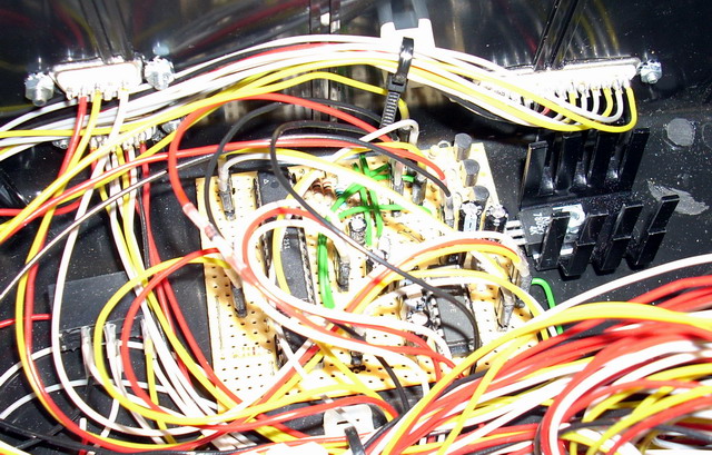
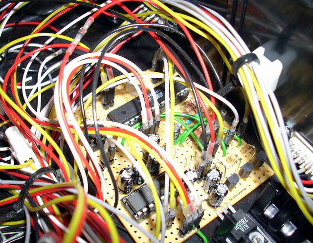
Photos
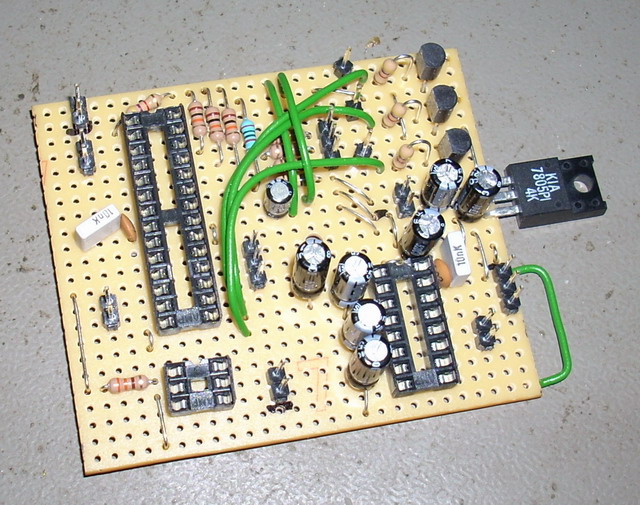
Schematic drawing
Parts list
- 1 × AVR ATmega8-16PU, DIL-28, 16 MHz, 23 I/Os
- 5 × Capacitor, aluminium electrolytic, 1 µF, 50V
- 1 × Capacitor, aluminium electrolytic, 10 µF, 25V
- 2 × Capacitor, aluminium electrolytic, 47 µF, 25V
- 2 × Capacitor, ceramic, 1 nF, 100V
- 2 × Capacitor, metallized polyester foil, 10 nF, (0.01 µF)
- 1 × DIL socket, 16-pin, 7.62mm
- 1 × DIL socket, 28-pin, 7.62mm
- 1 × DIL socket, 6-pin, 7.62mm
- 1 × Diode, small signal, 1N4148/Ph
- 1 × Heat conducting film for heatsink, Adhesive, TO220
- 1 × Heatsink, 15K/W @ 4W, 28mm 7g, TO220
- 1 × Optocoupler, single, CNY17F-3, DIL-6
- 32 cm2 PCB, stripboard, 100x160mm, 160cm2
- 4 × Resistor, carbon film, 0.25W, 330 Ω, 5%
- 4 × Resistor, carbon film, 0.25W, 4.7 kΩ, 5%
- 3 × Resistor, carbon film, 0.25W, 10 kΩ, 5%
- 1 × Resistor, carbon film, 0.25W, 100 kΩ, 5%
- 1 × Resistor, metal film, 0.6W, 20 kΩ, 1%
- 1 × RS232 interface, MAX232CPE, dual
- 1 × Spacer, round unthreaded, 3mm, Ø6mm, Delrin
- 17 × Straight pin header, female, Single row, 2.54mm
- 24 × Straight pin header, male, Single row, 2.54mm
- 3 × Transistor, NPN, 100 mA, 45V, 0.5W, BC547B
- 1 × Voltage regulator +5V, 1 A, 7805PI
Last commit 2024-11-11, with message: Add lots of tags to posts.
All posts in Rack box project series
- Parallel port I/O module
- Power supply and fuse monitoring module, AVR
- Monitored fuse box, 6 channels
- Stack lights and horn controller — with AVR
- Mute and light controller for the Rack box — AVR module
- Monitored fuse box, 4 channels
- Module heartbeat monitor, 6 inputs — AVR
- Controller for lights and relays — AVR driven
- Emergency power off controller — controlled by 555 timers
- Fan controller with LCD — AVR powered
- Sound alarm control unit — AVR module
- Multiplexer output extender
- Multi-purpose AVR module
- Electric heater and timer controller — AVR
- Module heartbeat monitor, 15 inputs — LCD and AVR
- Serial port I/O module with 11 inputs — AVR
- Serial port I/O module with 9 in and outputs — AVR
- Serial interface for emergency power off — AVR
- Status panel for the Rack box project
- Intruder alarm system controller — AVR
- Serial port I/O module with 15 inputs — AVR
- Serial interface module, with analog and digital I/O — AVR
- The rack box project — an overview