This post is part of the Rack box project series.
Controlling mute and lights in the rack box project. Uses an AVR ATtiny2313 microcontroller.
Table of contents
Details
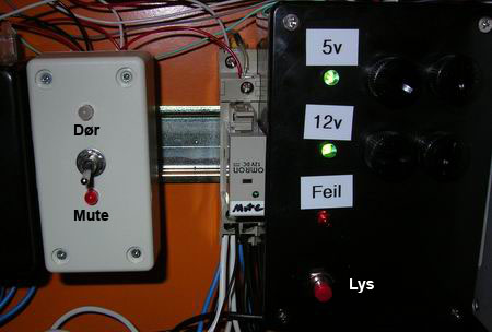
This simple controller takes care of a few small tasks in the Rack box. It controls the system mute function, the lights inside, and the door sensor of the Rack box.
When the door is opened the light turns on automatically, and stays on for five minutes. The light can also be turned on manually with a switch, the light is then active for 30 minutes, or until the door is closed. Door N.O and N.C signals is made available for other modules.
Mute
When system mute (quiet mode) is active, sound alarms and the stack light is deactivated. Errors are only shown in Serial Client and on the Rack status panel. Mute can be enabled manually or with the computer, using the Serial I/O system. A timer automatically enabled the system mute at night.
On weekdays; mute is activated at 11 PM and deactivated at 9 AM. In the weekend; it is activated at 1 AM and deactivated 11 AM.
Crontab example for Linux:
01 23 * * 0-4 root /var/www/ctrl_files/turn_port 4 1 #weekday on
01 01 * * 0,6 root /var/www/ctrl_files/turn_port 4 1 #weekend of
01 09 * * 1-5 root /var/www/ctrl_files/turn_port 4 0 #weekday off
01 11 * * 0,6 root /var/www/ctrl_files/turn_port 4 0 #weekend off
I/O
Inputs
- Mute switch
- Mute auto signal from timer
- Light switch
- Door switch
Outputs
- Mute relay
- Lights
- Door N.O
- Door N.C
- Mute LED
- Life-signal to Module heartbeat monitor
- Life-light
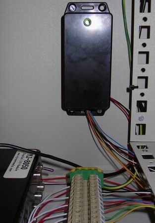
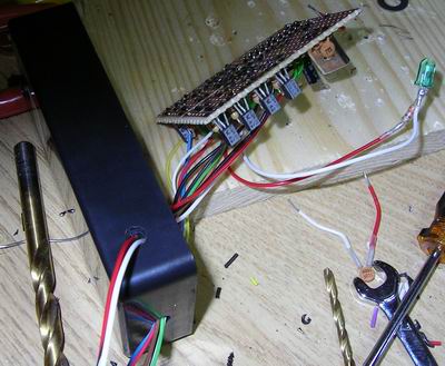
Wires
Side
- Red 5V+
- White 0V
- Black Life-signal (out)
Bottom
- Yellow Mute switch (in)
- Green Mute auto signal (in)
- Orange Light switch (in)
- Brown Door switch (in)
- Red Mute relay (out)
- Blue Lights (out)
- White Door N.O (out)
- Black Door N.C (out)
- Black (clear) Mute LED (out)
Source code
- Bascom-AVR source is available in a git repository:
- https://github.com/thomasjsn/AVR-Rackbox-mute-light-controller
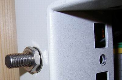
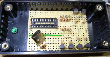
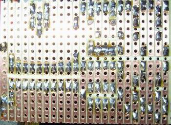
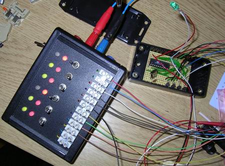
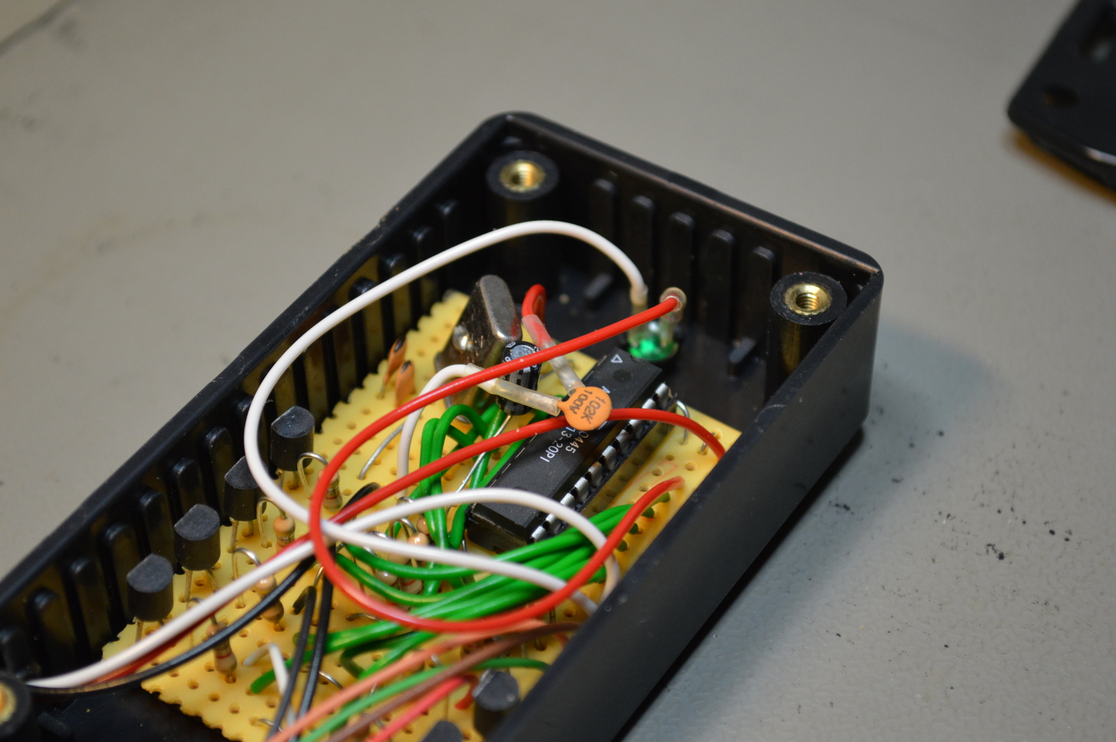
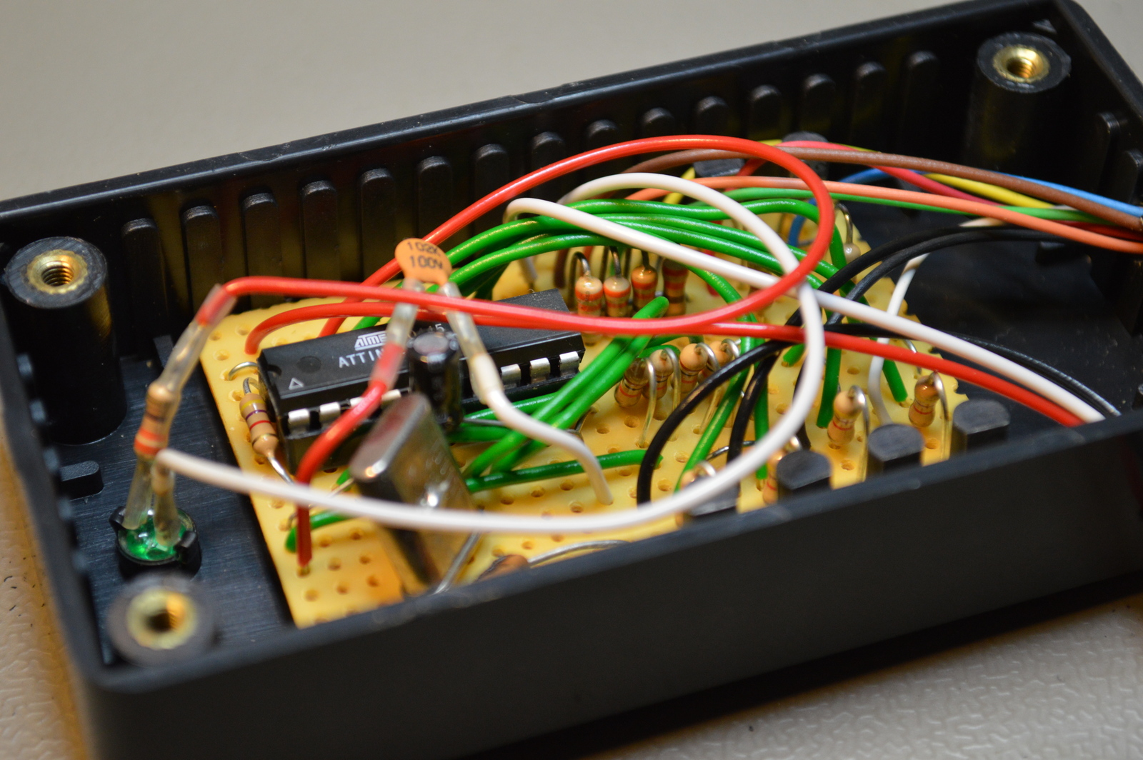
Photos

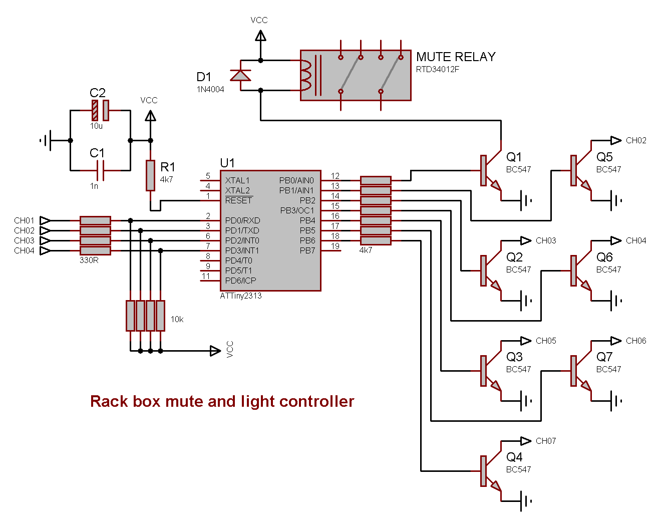
Schematic drawing
Parts list
- 1 × AVR ATtiny2313-20PU, DIL-20, 20 MHz, 18 I/Os
- 1 × Capacitor, aluminium electrolytic, 10 µF, 25V
- 2 × Capacitor, ceramic, 22 pF, 100V
- 1 × Capacitor, ceramic, 1 nF, 100V
- 1 × DIL socket, 20-pin, 7.62mm
- 1 × Enclosure, plastic (1591 FL), 100x50x25mm, flange
- 1 × LED 5mm coloured clear, Green, 2.1V, 20mA, 30mcd, 10°
- 1 × LED holder 5mm, RTC51, black plastic
- 32 cm2 PCB, stripboard, 100x160mm, 160cm2
- 1 × Quartz crystal oscillator, 4 MHz
- 5 × Resistor, carbon film, 0.25W, 330 Ω, 5%
- 7 × Resistor, carbon film, 0.25W, 4.7 kΩ, 5%
- 4 × Resistor, carbon film, 0.25W, 10 kΩ, 5%
- 6 × Transistor, NPN, 100 mA, 45V, 0.5W, BC547B
Last commit 2024-11-11, with message: Add lots of tags to posts.
All posts in Rack box project series
- Parallel port I/O module
- Power supply and fuse monitoring module, AVR
- Monitored fuse box, 6 channels
- Stack lights and horn controller — with AVR
- Mute and light controller for the Rack box — AVR module
- Monitored fuse box, 4 channels
- Module heartbeat monitor, 6 inputs — AVR
- Controller for lights and relays — AVR driven
- Emergency power off controller — controlled by 555 timers
- Fan controller with LCD — AVR powered
- Sound alarm control unit — AVR module
- Multiplexer output extender
- Multi-purpose AVR module
- Electric heater and timer controller — AVR
- Module heartbeat monitor, 15 inputs — LCD and AVR
- Serial port I/O module with 11 inputs — AVR
- Serial port I/O module with 9 in and outputs — AVR
- Serial interface for emergency power off — AVR
- Status panel for the Rack box project
- Intruder alarm system controller — AVR
- Serial port I/O module with 15 inputs — AVR
- Serial interface module, with analog and digital I/O — AVR
- The rack box project — an overview