This post is part of the Rack box project series.
Detects and alerts if any of the monitored modules goes silent; meaning their heartbeat stops. Uses an AVR AT90S8515 microcontroller.
Table of contents
Details
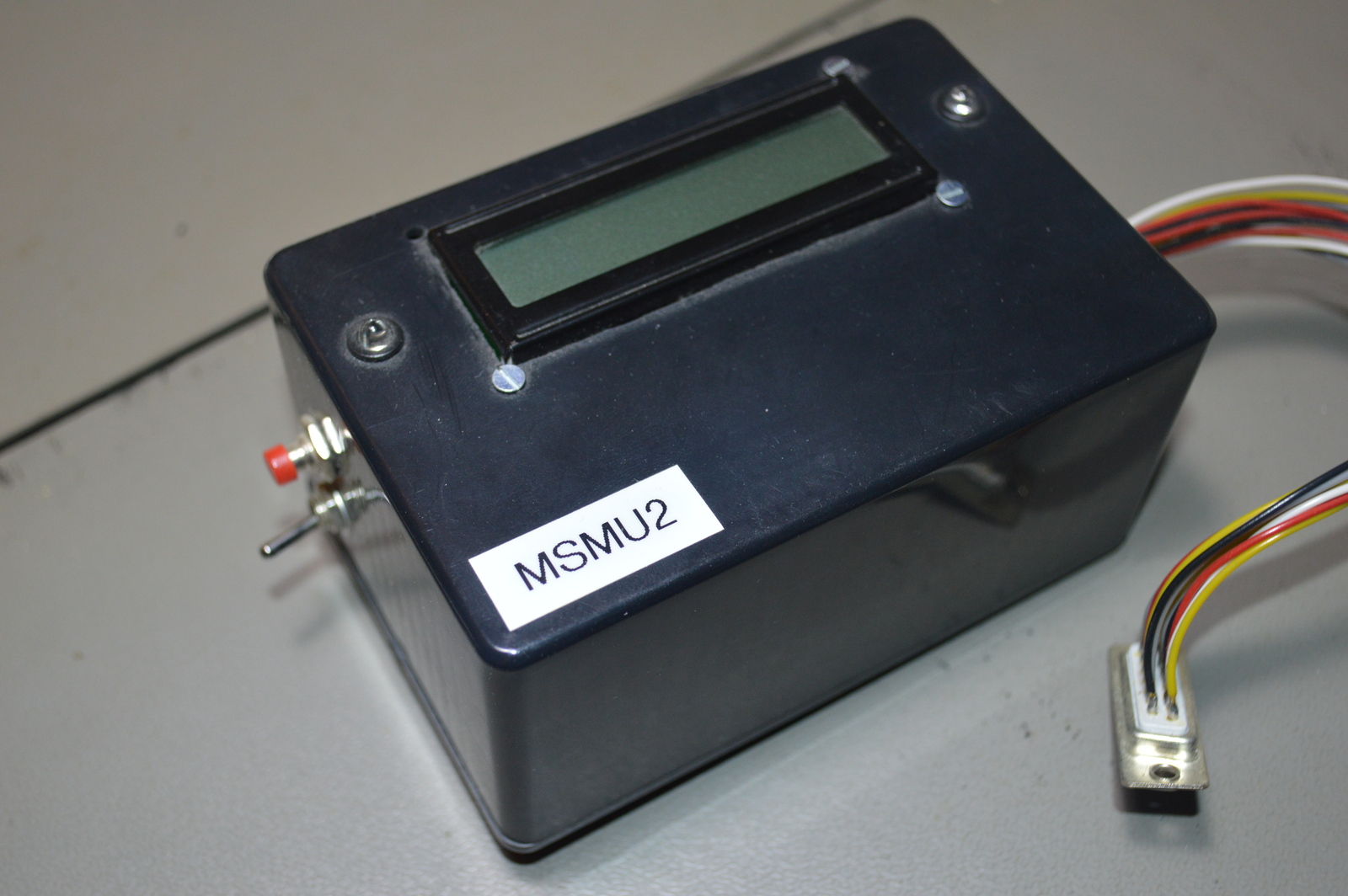
As I started putting more and more modules into my rack box project, the previous monitoring module quickly ran out of inputs. I needed to build something bigger and better. I realized that using LEDs to show module status just wasn’t practical as the number of inputs increased. So this unit shows the module statuses on an LCD display instead, and has 15 inputs.
If you’ve read about my first module heartbeat monitor you already know why I built it, if not; here is a recap: I needed a way to know that the modules inside the rack box project were not only powered, but running. Monitoring their heartbeat output was the solution.
If more than 10 seconds passed, without receiving a heartbeat this monitor unit would go into alarm state. A blue LED would flash, and the LCD display would show which module failed.
10 FAIL!
All alarms had to be manually reset, even if the heartbeat came back. The reason for this was so that I would see it if a module had been dead for some time, but came back by itself. This would still indicate a problem with that module.
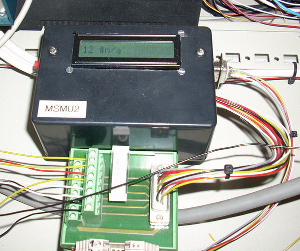
If a heartbeat was not detected at all after a reset, that input was marked as inactive and #n/a was shown on the LCD. Inactive inputs did not produce alarms.
4 #n/a
The remaining time was also shown on the LCD display, it was split into half seconds; so 20 meant that there was 10 seconds left.
1 Ok>20
Video
This quick demo first shows all inputs as #n/a, meaning no heartbeat signal received so the inputs are disabled. After I send a few signals, the inputs will timeout after 10 seconds if no further signals are received. A timed out input will be marked FAIL! until manually reset.
I/O
Inputs
- PA2 Module 1
- PA3 Module 2
- PC2 Module 3
- PC3 Module 4
- PC4 Module 5
- PC5 Module 6
- PC6 Module 7
- PC7 Module 8
- PD0 Module 9
- PD1 Module 10
- PD2 Module 11
- PD3 Module 12
- PD4 Module 13
- PD5 Module 14
- PD6 Module 15
- PD7 Reset
Outputs
- PB0 LCD Db7
- PB1 LCD Db6
- PB2 LCD Db5
- PB3 LCD Db4
- PB6 LCD E
- PB7 LCD Rs
- PA0 Module error (to Signal and lights controlling unit)
- PA1 Lifelight
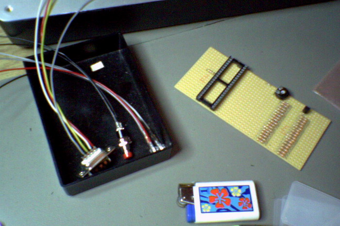
Connectors
D-Sub 9-pin
- 5v
- 0v
- Reset
- Module error LED
D-Sub 15-pin
- Module 1 → 15
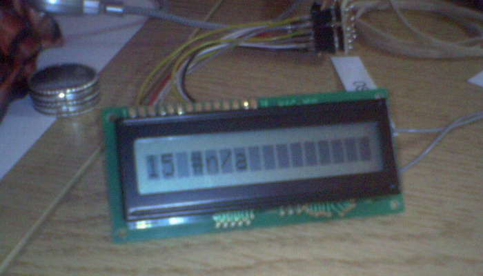
LCD display
I used a broken LCD display on this module, of the 16 characters on the display only the first 8 worked. Below are the different messages and statuses shown on the display.
12345678
MSMU #2
Running
1  Ok>21
4  #n/a
10 FAIL!
Reset!
Source code
- Bascom-AVR source is available in a git repository:
- https://github.com/thomasjsn/AVR-Module-heartbeat-monitor-LCD
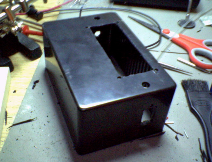
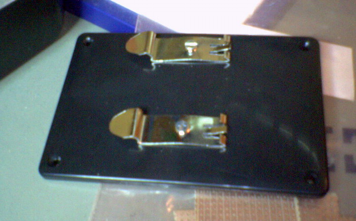
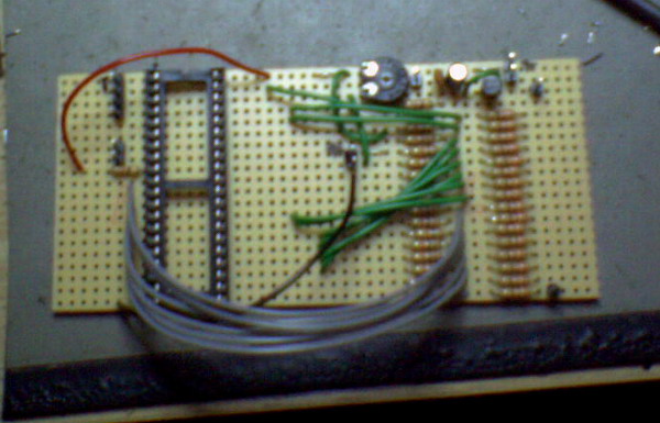
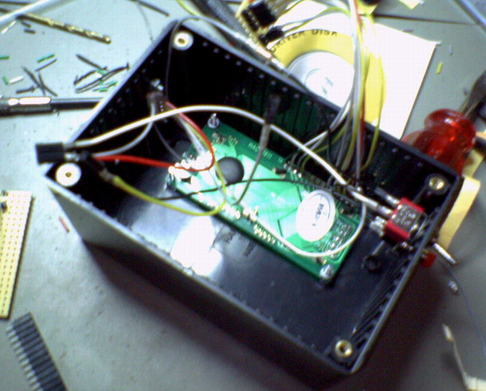
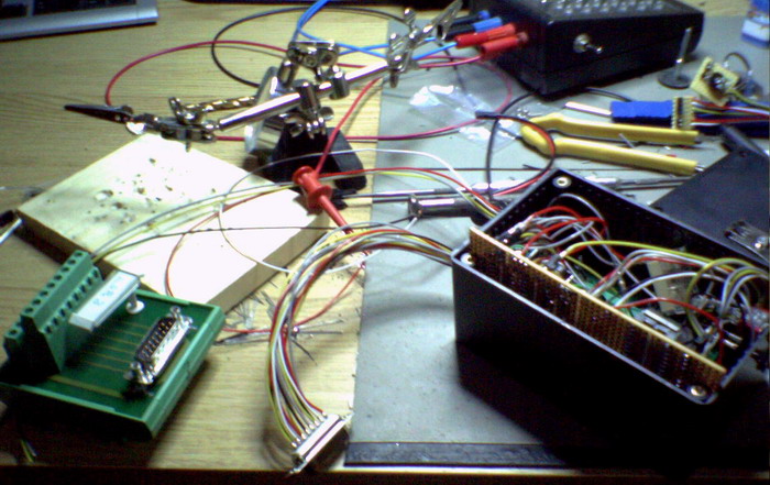
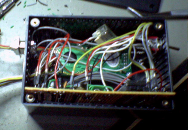
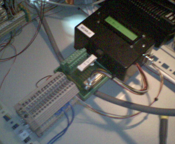
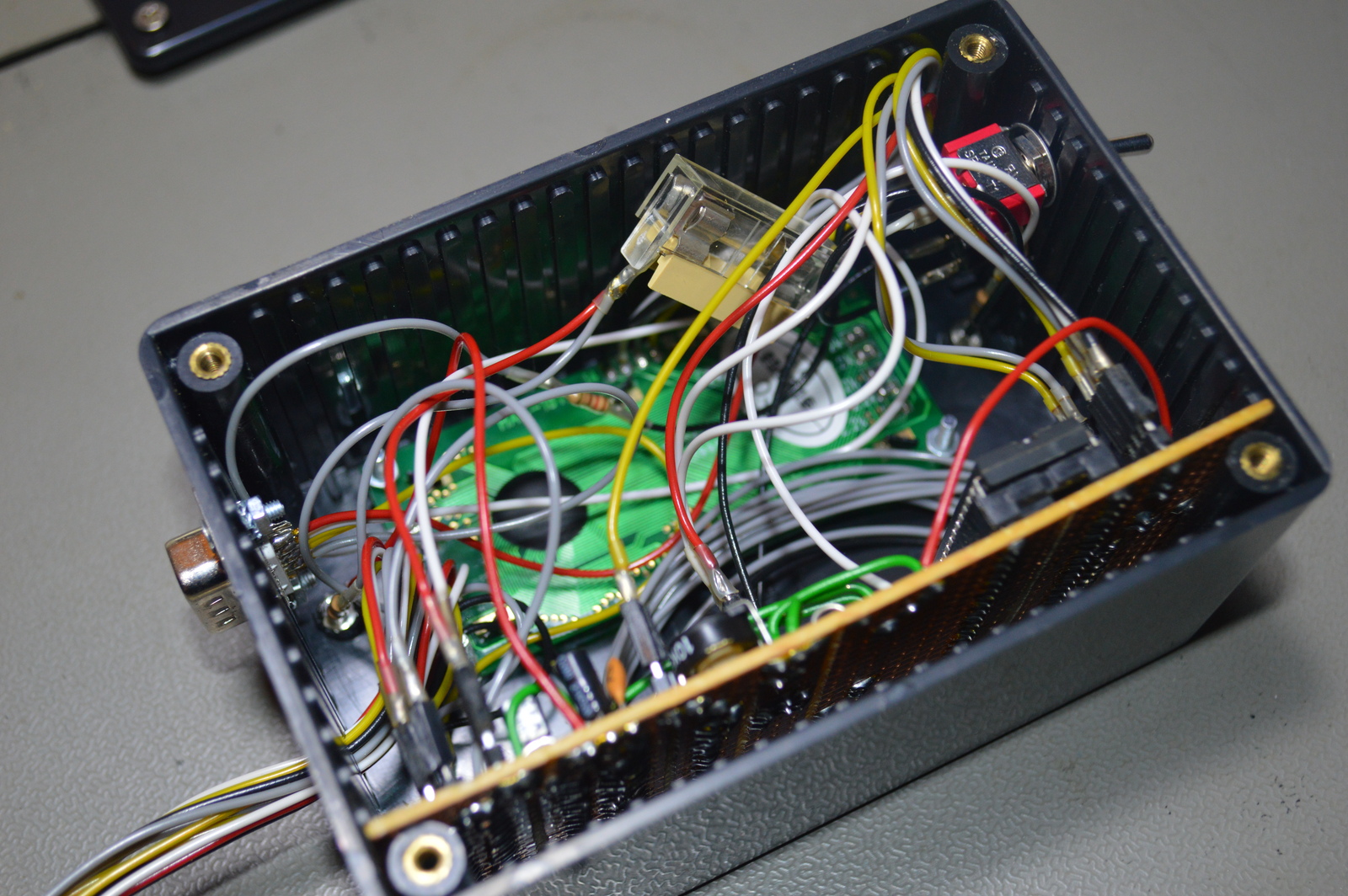
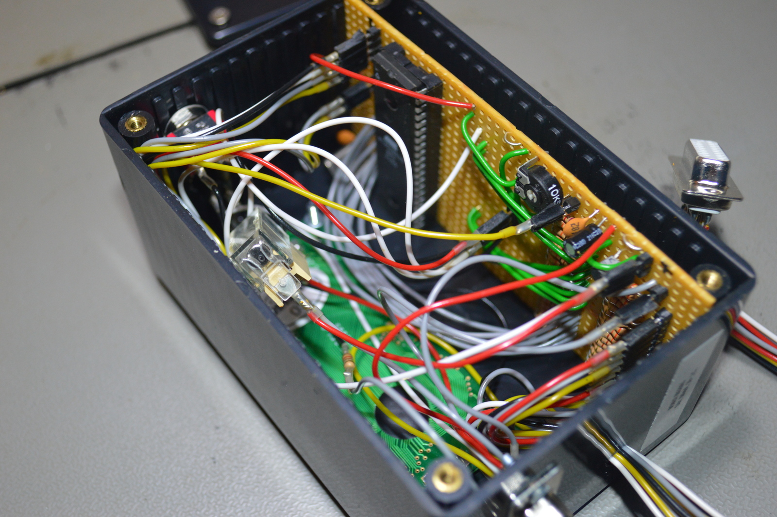
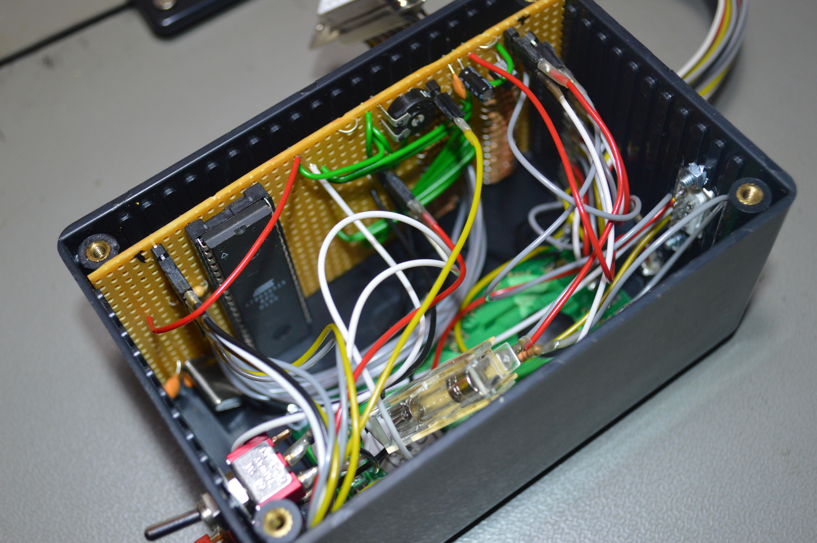
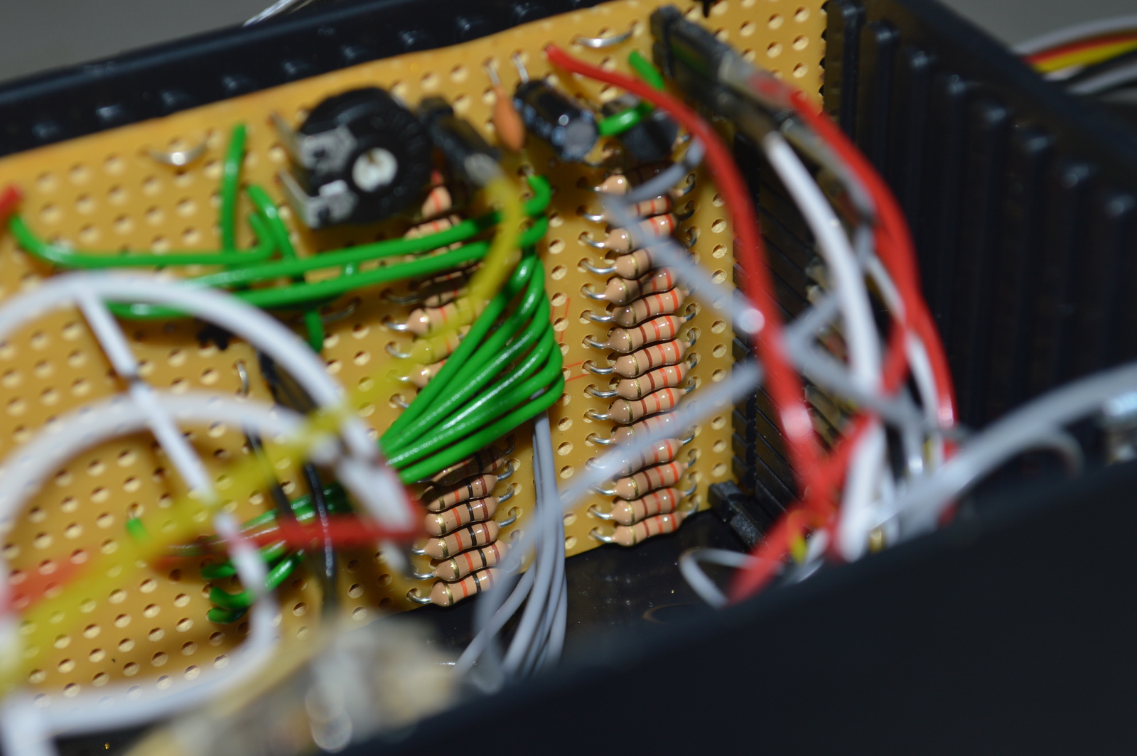
Photos
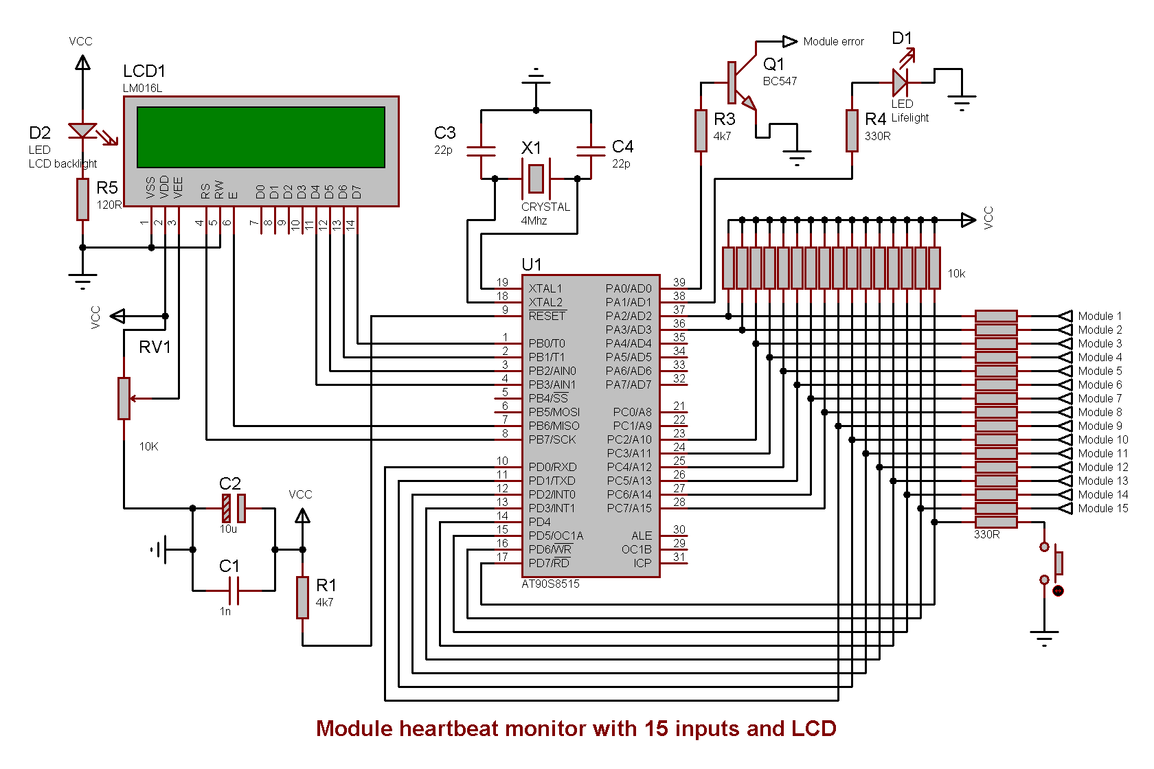
Schematic drawing
Parts used
- 1 × AVR AT90S8515-8PC, DIL-40, 8 MHz, 32 I/Os
- 1 × Capacitor, aluminium electrolytic, 10 µF, 25V
- 2 × Capacitor, ceramic, 22 pF, 100V
- 1 × Capacitor, ceramic, 1 nF, 100V
- 1 × D-sub soldering cups, 15 pin female
- 1 × D-sub soldering cups, 9 pin male
- 1 × DIL socket, 40-pin, 15.24mm
- 2 × Diode, small signal, 1N4148/Ph
- 1 × Enclosure, plastic (1591), 120x80x59mm
- 1 × Fuse 5x20 mm, 500 mA, fast-acting
- 1 × Fuse holder, open, PCB, 5x20mm
- 1 × Fuse holder, open, PCB, Protective cover
- 1 × LCD display, dot matrix, 16x1, LED green
- 1 × LED 5mm clear, Blue, 4.9V, 20mA, 350mcd, 12°
- 1 × LED 5mm clear, Green, 2.1V, 20mA, 385mcd, 6°
- 2 × LED holder 5mm, RTC51, black plastic
- 2 × Mounting bracket, DIN rail, Metal
- 1 × Quartz crystal oscillator, 4 MHz
- 1 × Resistor, carbon film, 0.25W, 120 Ω, 5%
- 18 × Resistor, carbon film, 0.25W, 330 Ω, 5%
- 2 × Resistor, carbon film, 0.25W, 4.7 kΩ, 5%
- 16 × Resistor, carbon film, 0.25W, 10 kΩ, 5%
- 1 × Switch, push-button, 1-pole, 1A, 50VAC, off-(on)
- 1 × Switch, toggle, 1-pole, micro, on-on
- 1 × Transistor, NPN, 100 mA, 45V, 0.5W, BC547B
- 1 × Trimmer, carbon, 10 kΩ, horizontal
Last commit 2024-11-11, with message: Add lots of tags to posts.
All posts in Rack box project series
- Parallel port I/O module
- Power supply and fuse monitoring module, AVR
- Monitored fuse box, 6 channels
- Stack lights and horn controller — with AVR
- Mute and light controller for the Rack box — AVR module
- Monitored fuse box, 4 channels
- Module heartbeat monitor, 6 inputs — AVR
- Controller for lights and relays — AVR driven
- Emergency power off controller — controlled by 555 timers
- Fan controller with LCD — AVR powered
- Sound alarm control unit — AVR module
- Multiplexer output extender
- Multi-purpose AVR module
- Electric heater and timer controller — AVR
- Module heartbeat monitor, 15 inputs — LCD and AVR
- Serial port I/O module with 11 inputs — AVR
- Serial port I/O module with 9 in and outputs — AVR
- Serial interface for emergency power off — AVR
- Status panel for the Rack box project
- Intruder alarm system controller — AVR
- Serial port I/O module with 15 inputs — AVR
- Serial interface module, with analog and digital I/O — AVR
- The rack box project — an overview