This post is part of the DIY Security Alarm series.
In November last year — I started building a DIY security alarm system, using a Raspberry Pi as the controller. My plan was to make a self-sustained system, using proper alarm hardware — like PIR sensors and sirens.
Integration with Home Assistant would be an add-on, not a requirement. I wanted the system to be as redundant and fault-tolerant as I could make it.
This is a pretty long story, with some twists and turns — let’s get into it 👇
Table of contents
Introduction
This is one blog post I’ve been putting of for a while — there is just so much to tell, and the system is still a work-in-progress. I will be splitting it up into multiple posts; starting at the beginning 🙂
Why?
I’ve wanted a security alarm system for a while now, but I loathe the companies providing it here in Norway. Yes Verisure and Sector Alarm — I’m talking about you guys.
They charge an absurdly high monthly fee, and seems dedicated to get as much money from you as they possibly can. While offering no integrations with things like Home Assistant — they want you vendor locked to their system.
To add insult to injury; they both got fined last year for cooperation that restricts competition 😞 Combined they got fined 1.233 million NOK.
Making my own alarm system seemed like a cool challenge, that would eventually result in something useful 🙂
The plan
Like I wrote; my plan changed multiple times. But the overall goal stayed the same, let’s go through that now.
I wanted to use a controller I could SSH into and easily make changes and adjustments. Enter the Raspberry Pi — it has a generous amount of GPIO pins, and libraries to make them easily accessible from a Python script.
I started with a Raspberry Pi Zero W, but later changed to a Raspberry Pi 3+. I needed something a bit more powerful, and with wired Ethernet — I didn’t want to rely on Wi-Fi, especially inside a grounded metal cabinet 😛
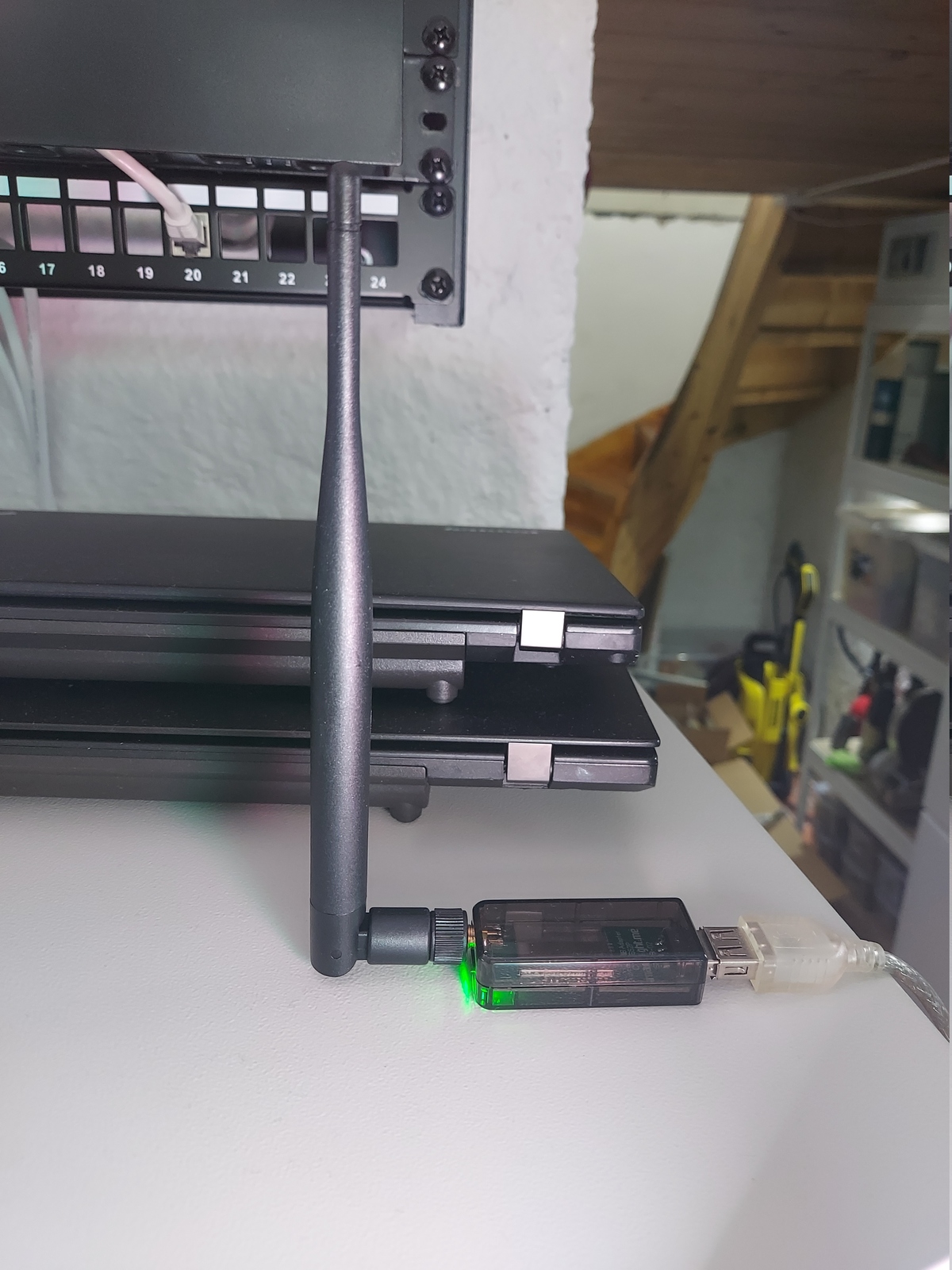
Next I wanted the ability to use any kind of sensor and hardware — wired and wireless. Wired things would connect to the Raspberry Pi GPIO pins, and wireless through Zigbee using Zigbee2MQTT as I described in the previous post in this series.
I’m a firm believer that everything that can be hardwired — should be hardwired, but for some things, like door sensors, it’s just not practical.
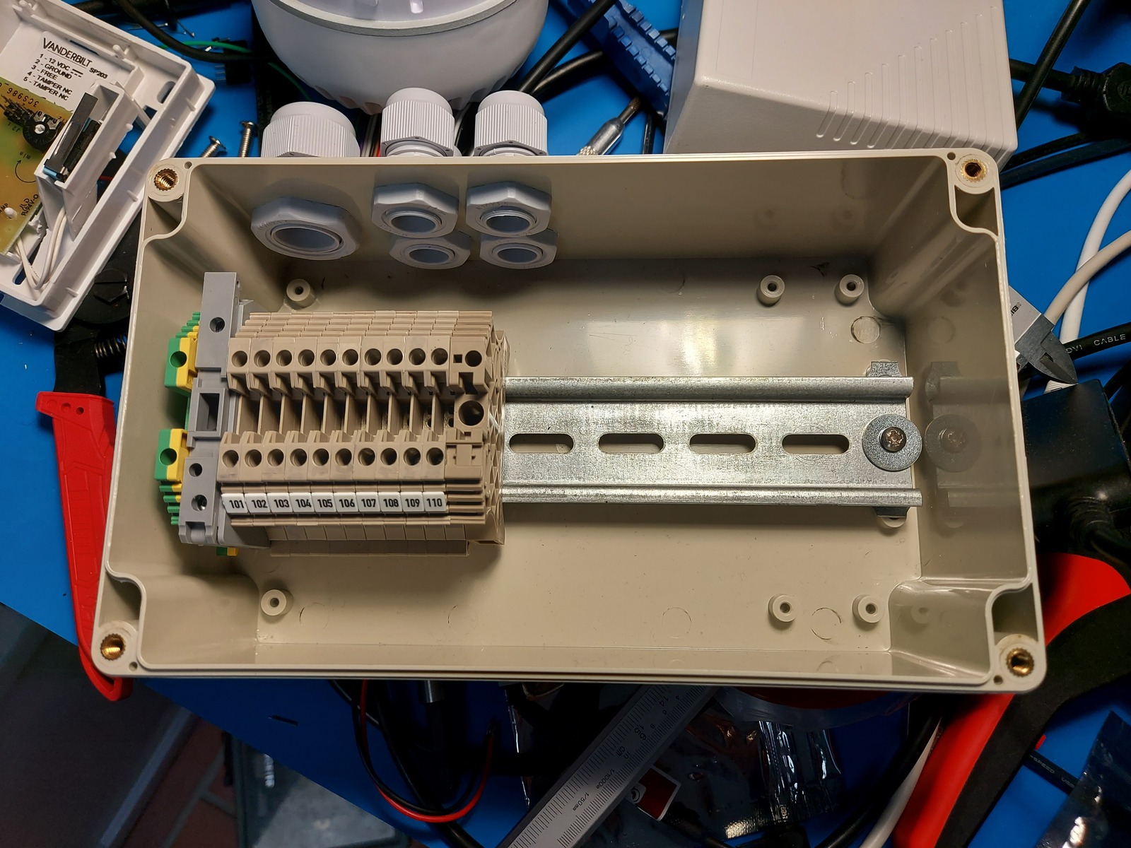
For the enclosure I started with a 200×120×75mm plastic box, but in time I realized that it wasn’t going to be big enough. Then I ordered a 400×300×150 mm metal cabinet — but soon after; I decided that the system needed a backup battery, and I needed an ever bigger enclosure.
So I ordered another metal cabinet, measuring 500×300×210 mm — and this is the one I ended up using 🙂
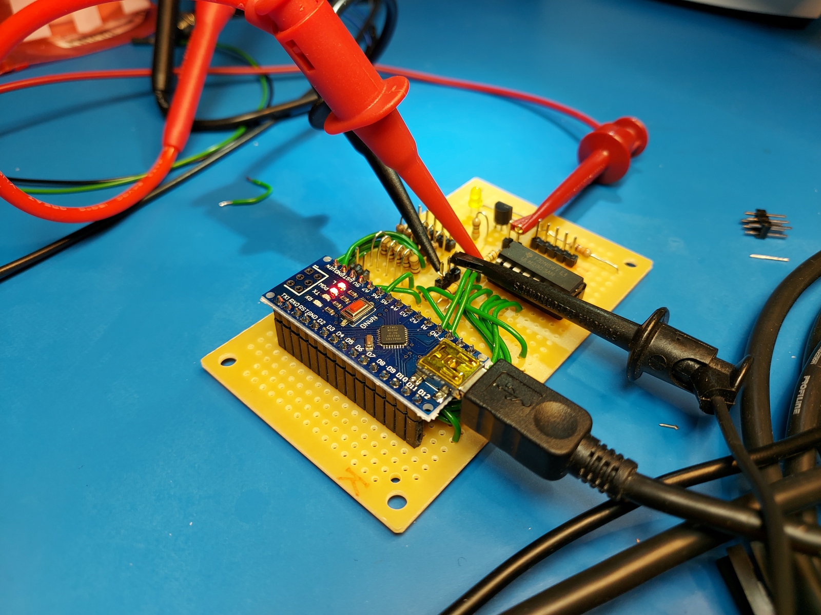
Later on in the project I started worrying about the Python script dying while the sirens were turned on — which would have been a disaster. So I decided to include an Arduino microcontroller as a monitoring and fail-safe solution, but I think that story is better suited for a later blog post in this series.
Raspberry Pi
As the main controller; I’m using a Raspberry Pi 3+ — it has a decent CPU and 1 GB RAM, together with an Ethernet and USB ports.

On the Raspberry Pi I:
- Added a new user, and deleted the default user
pi - Installed all updates and set the time zone
- Install Supervisor, Vim, and Git
- Installed Python libraries for MQTT and serial communication
- Added my user to the
gpioanddialoutgroups - Made a configuration file for Supervisor to make sure the alarm script was always running
$ sudo userdel -r pi
$ sudo apt update && sudo apt upgrade
$ sudo dpkg-reconfigure tzdata
$ sudo apt install supervisor vim git

$ sudo apt install python3-paho-mqtt python3-serial
$ sudo adduser hebron gpio dialout

$ sudo cp supervisor/alarm.conf /etc/supervisor/conf.d/
$ sudo systemctl restart supervisor.service
My Supervisor program definition looks like this:
[program:alarm]
command=python3 alarm.py
directory=/home/hebron/rpi-alarm
autostart=true
autorestart=unexpected
user=hebron
stderr_logfile=syslog
stdout_logfile=syslog
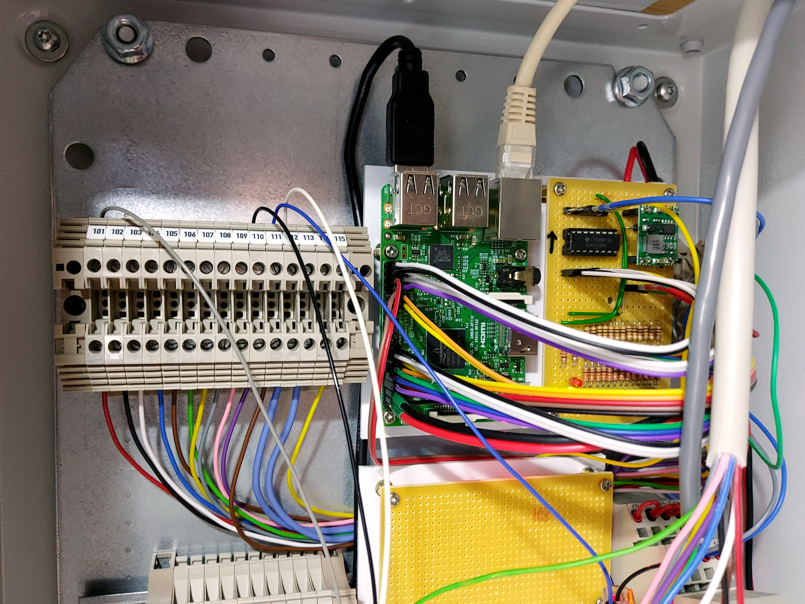
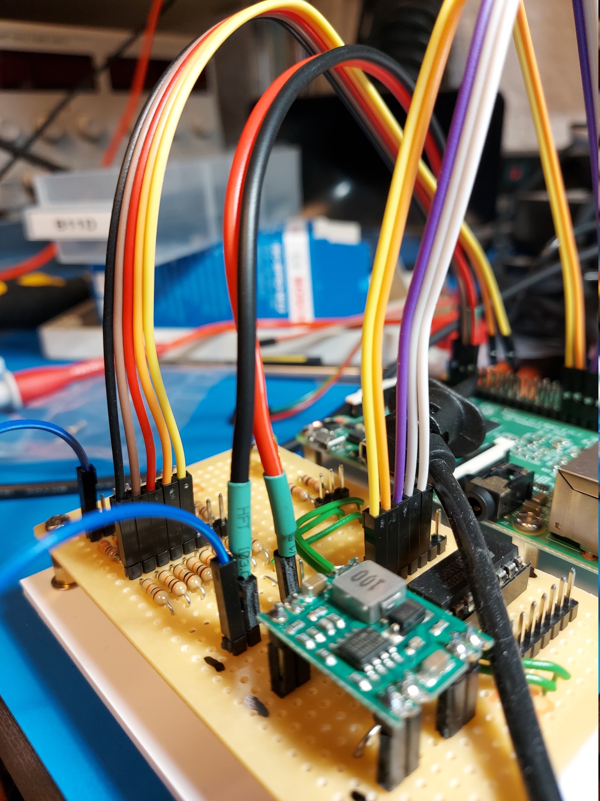
Electronics
I made a circuit board to step down 12 volts to 5 — for the Raspberry Pi, and handle all the inputs and outputs. 7 outputs and 8 inputs, which I later expanded to 8 outputs and 13 inputs 🙂
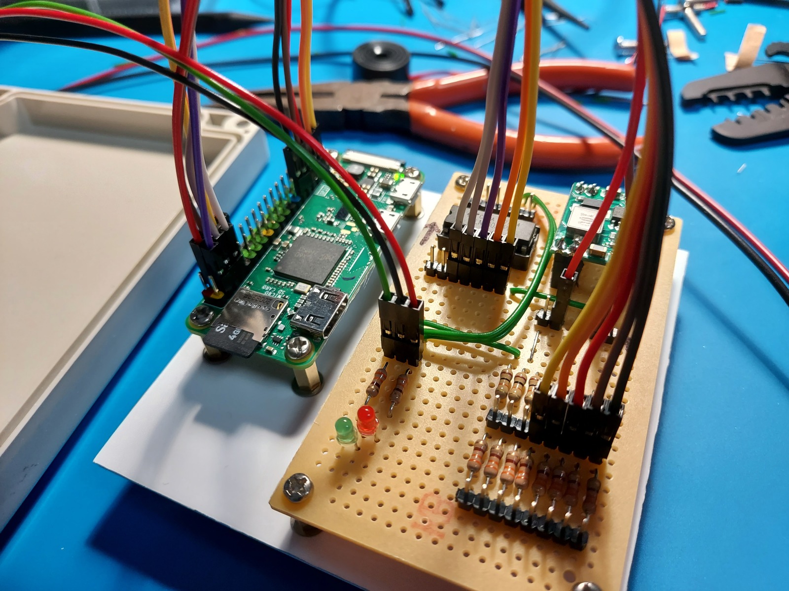
The board has red and green LEDs, showing the status of the system:
- Slow flashing green: everything OK, unarmed
- Fast flashing green: everything OK, armed
- Flashing red: there is a problem
- Steady or no light: dead/script not running 💀
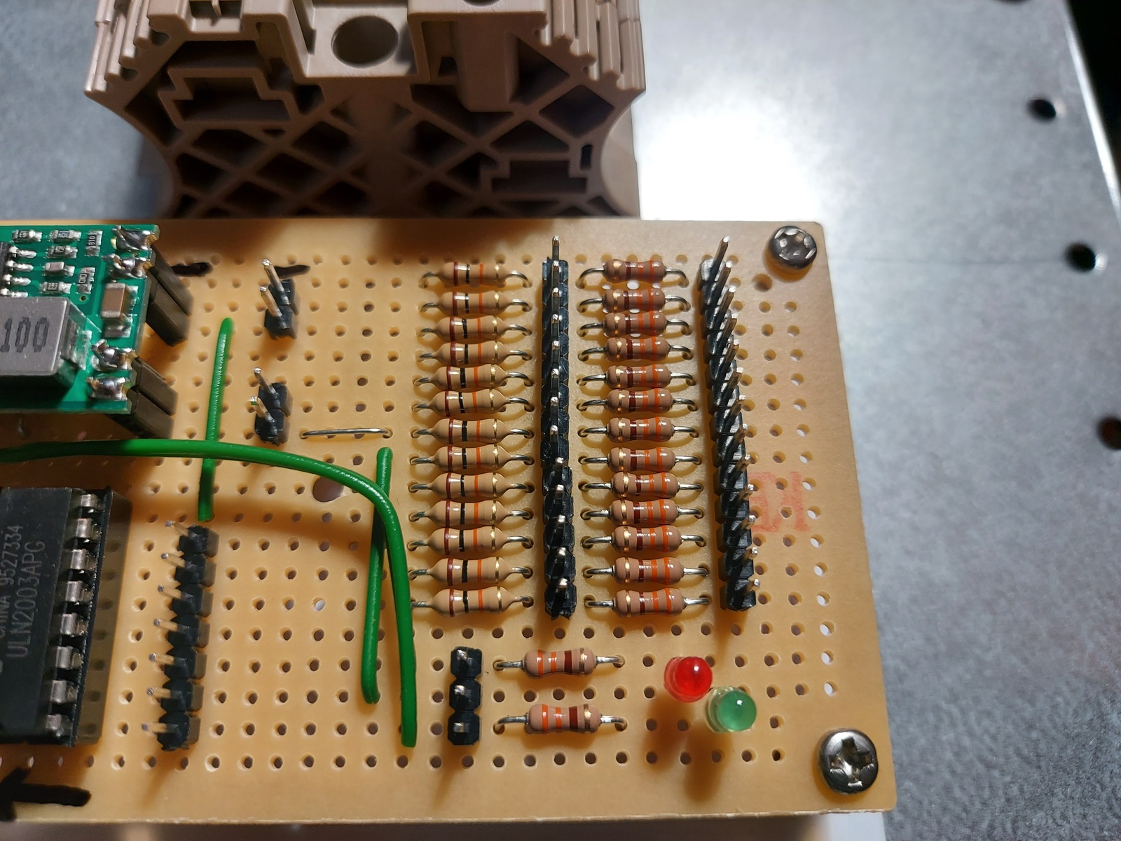
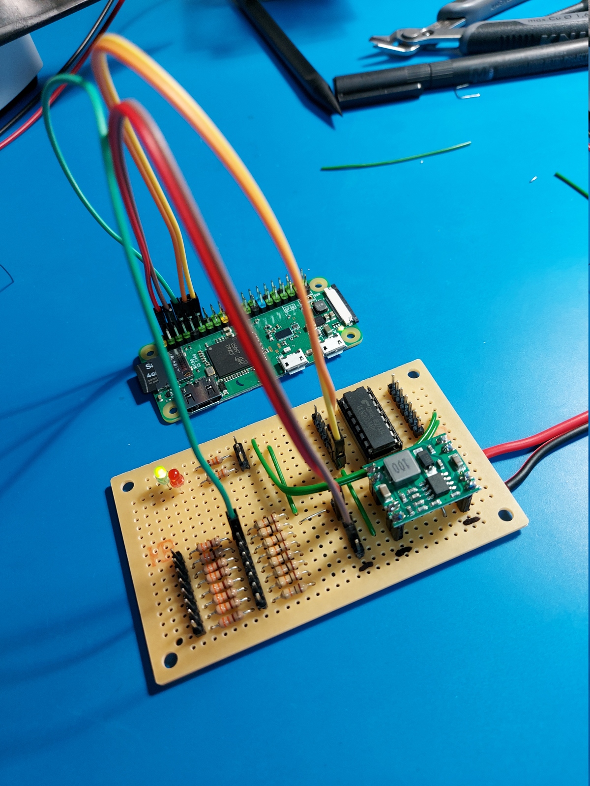
On the interface board is:
- Darlington-driver for outputs
- Pull up resistors for inputs (330 Ω and 10 kΩ)
- Voltage step-down buck converter, with a diode for reverse polarity protection
The two boards are connected with Dupoint jumper wires. I had to use 18 AWG wire for the power — to prevent the voltage dropping below 5 V. Both cards are mounted to a styrene plastic sheet using brass stand-offs. On the backside is a DIN rail mounting bracket.
Here are the parts I used for the Raspberry Pi, and power and interface board:
- 1 × Darlington-driver, 7 step, ULN2003A, DIL16, In: 2.7K/5V
- 1 × DIL socket, 16-pin, 7.62mm
- 1 × Diode, rectifier, 1 A, 400V, 1N4004
- 20 × Jump/dupont wire, female-female, 20cm, 2.54mm
- 1 × LED 3mm, Green, 1.9-2.1V, 20mA, 10000-12000mcd
- 1 × LED 3mm, Red, 1.9-2.1V, 20mA, 3000-4000mcd
- 1 × microSDHC card, Samsung EVO, 32GB, UHS-1, 100MB/s
- 2 × Mounting bracket, DIN rail, Plastic
- 1 × PCB, stripboard prototyping, 94x53mm, 50cm2
- 1 × Raspberry Pi 3 Model B, 1.2GHz Quad 64bit, 1GB RAM, BT, WLAN
- 15 × Resistor, carbon film, 0.25W, 330 Ω, 5%
- 1 × Resistor, carbon film, 0.25W, 4.7 kΩ, 5%
- 13 × Resistor, carbon film, 0.25W, 10 kΩ, 5%
- 8 × Stand-off PCB, M3, male-female, 10+6 mm, brass
- 19 × Straight pin header, female, Single row, 2.54mm
- 1 × Straight pin header, male, Dual row, 2.54mm
- 55 × Straight pin header, male, Single row, 2.54mm
- 125 cm2 Styrene plastic sheet, 3.2 mm
- 1 × Transistor, NPN, 100 mA, 45V, 0.5W, BC547B
- 1 × Voltage step-down buck converter, In: 7-28V, Out: 5V/3A
- 0.3 m Wire, stranded, 2-cores, 0.75 mm2, Red/Black
Below is an early test of the Python script on the Raspberry Pi Zero W, and Home Assistant integration:
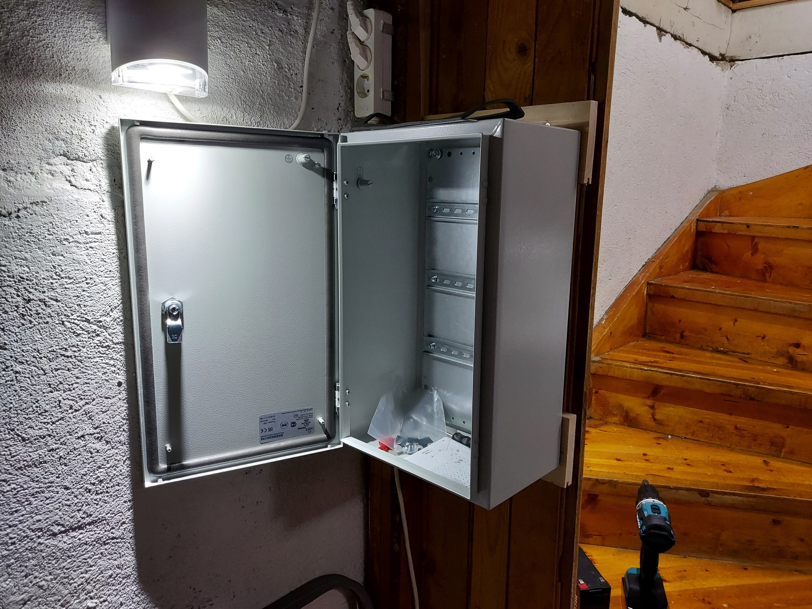
Enclosure
I’m delighted that I decided to get a large enclosure. There are more space efficient ways of doing it — but I like to have some room to work 🙂
The terminal blocks take up a fair bit of DIN-rail length, but having the wire connections clear and easy is definitely worth it.
I mounted three rows of DIN-rail:
- Sensor terminal blocks, Raspberry Pi, and interface board
- Output terminal blocks, auxiliary I/O, supporting controllers, and relays
- 230V, fuses, and power distribution
One strip-board on the 2nd row has been left unpopulated — the initial plan was to use an AVR microcontroller board for all the tamper circuits. But I’ve put that off for now.
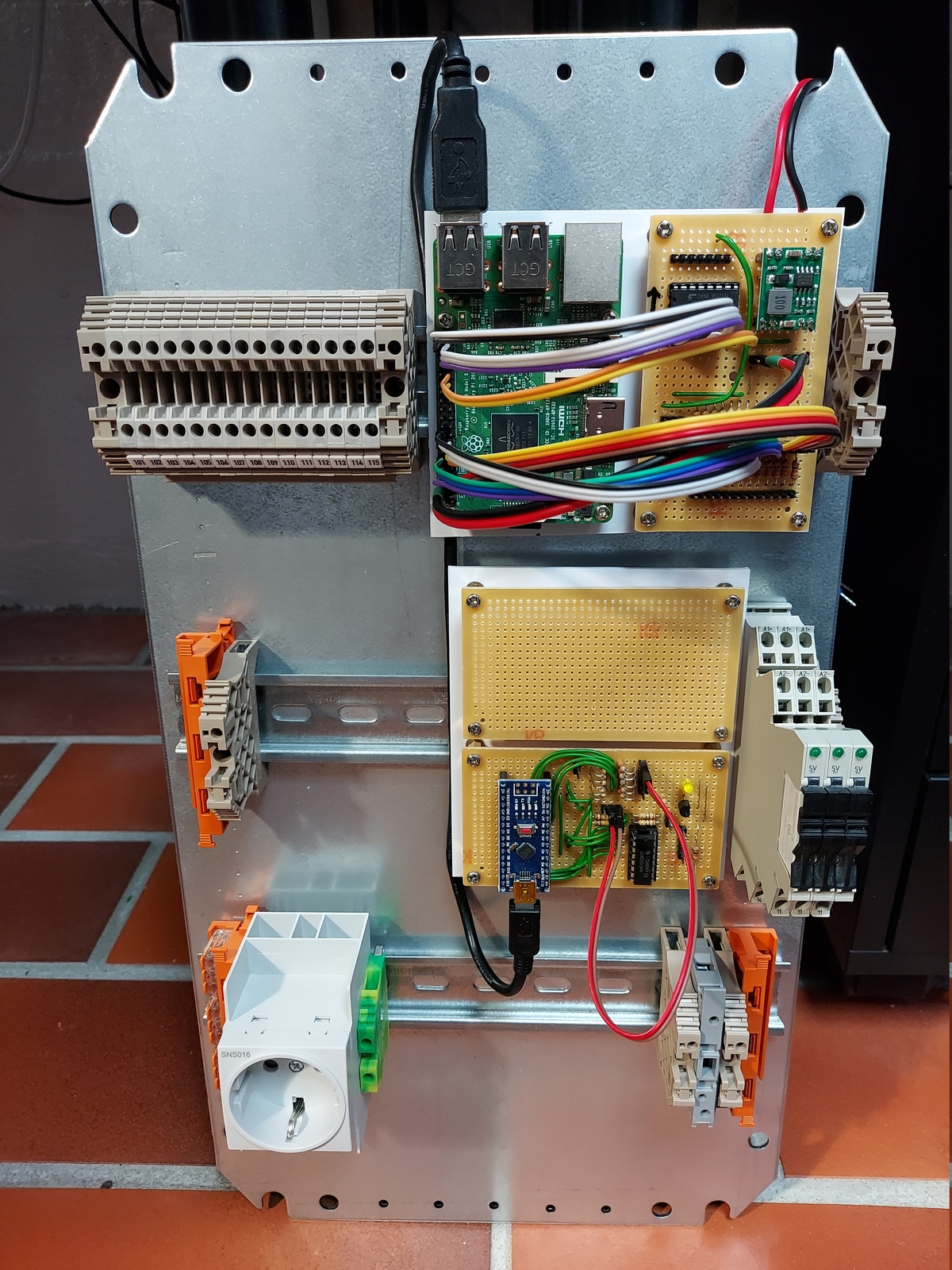
The cabinet has both a mounting and gland plate. A mounting plate is the removable plate that everything is mounted to — this is a huge advantage when doing the initial install.
The gland plate is a removable plate to drill holes for cable glands — being removable makes it a lot easier, as you can use a drill press. I’ve mounted my cabinet with the gland plate on top, since that’s where the cables will enter the cabinet.
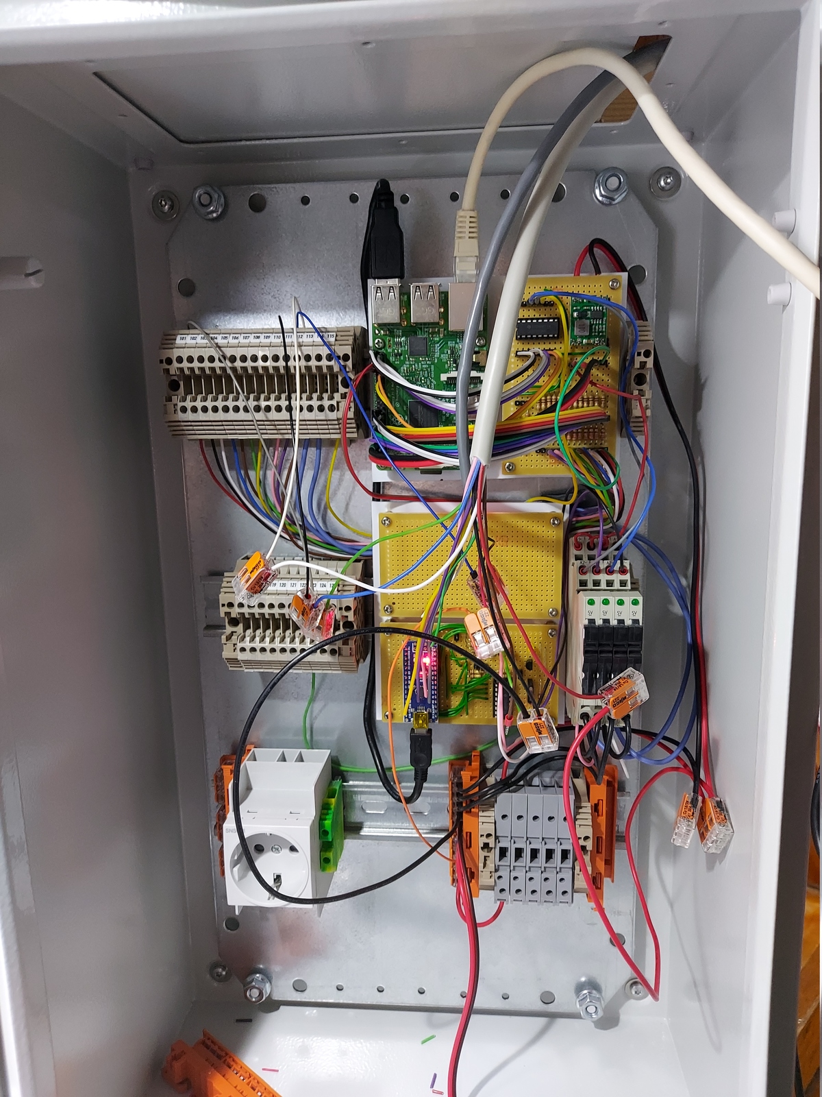
The 230 V power outlet is for a CTEK battery charger that will charge the backup battery. I’ve left enough space available to fit one, or two, 7.2Ah lead-acid batteries. I’ll write more about that later in the blog post series.
Excuse the current rat’s nest of cables, I’m still in the installation phase — or so I tell myself.
Operation
There is just too much going on to explain it all in one sitting, so I’ll cover more of the functionality in future blog posts. For now; I’ll briefly explain the core security alarm functions — armed home, and away — and a few supporting functions.
Features
There is a rough overview of the currently implemented features:
- Supports both hardwired and MQTT sensors and outputs
- Support for multiple MQTT alarm panels, with set states †
- Home Assistant integration with auto discovery
- Push messages using Pushover
- Heartbeat monitoring using Healthchecks
- Fail-safe and monitoring with an Arduino †
- Personal PIN-codes
- Configurable zones with delay and direct trigger
- Home and away arm mode, with configurable zones
- Water sensor support †
- Panic and emergency alarms
- Zone timers, to use as triggers in Home Assistant automations
- Front door open warning
- Several system checks
- Lead-acid battery backup, with charger †
Arming and disarming
The system supports multiple MQTT alarm panels — as well as the Home Assistant MQTT alarm control panel.
The panels have no knowledge of PIN codes — they only send what has been entered, along with the chosen action. The system checks if the received PIN code belongs to a user — if so, the action is valid.
If the wrong code is entered multiple times, a system fault is set — notifying the system owner.
Armed home
When the system is armed home; only the peripheral zones, such as doors and windows, are armed. The alarm will trigger immediately if any zones are opened, bypassing the entry delay.
Armed away
Both entry and exit delays are used when the system is armed away. All zones are monitored, but some have delay enabled.
If a zone with delay is activated the system will enter pending mode, aka entry delay, giving the user time to input the PIN code and disarm the system.
If a zone without delay is activated — the alarm will directly trigger, even when in pending mode.
Triggered mode
Triggered mode means the alarm has been triggered — the indoor siren start immediately, while the outdoor siren starts when ⅓ (one third) of the configured trigger time has passed.
So if the trigger time is 60 seconds, the outdoor siren will be delayed by 20 seconds.
Panic and emergency
If supported by the keypad; the system can also enter triggered mode on panic or emergency.
Panic will trigger the regular alarm, with sirens — while emergency only gives a short signal to confirm, but alerts by push message as usual.
Zone timers
Zone timers can be configured with one, or many zones, and a timeout value in seconds. They simplify the process of setting up automations in Home Assistant based on multiple zones, such as motion activated lights — based on several motion sensors.
A zone timer can be cancelled manually.
Door open notification
If the front door is left open — a short buzzer signal will sound, as a reminder to close the door. The buzzer signal will gradually increase in intensity if the door is left open.
System checks
The system keeps track of several statuses, and a notification is sent if a problem is detected.
The following conditions are monitored:
- Backup battery voltage
- Cabinet temperature
- Number of failed PIN code attempts
- System and zone tamper
- Heartbeat ping
- Mains power present
- MQTT connected
- Sensors are alive
- Sensor link quality and battery
- Siren relay works
- Zigbee bridge available
Healthchecks is used to externally monitor the system, and will notify if it stops receiving heartbeat pings.
Sensors, sirens, and keypad
I consider all wireless communication to be varying degrees of unreliable — wired is always better than wireless. The wired sensors and devices are very reliable, have a battery backup, and no external dependencies.
While the wireless Zigbee sensors can have communication problems — and relies on a Docker container running Zigbee2MQTT, a MQTT broker, and network communication between the mentioned hosts and the Raspberry Pi. Backup power is provided by a UPS, but the run-time is limited.
I’ve tried to design the system in such a way that the core functionality will be operational — despite all external systems being offline. Even operate for days on battery backup.
Wireless hardware
I’m currently using a Climax KP-23EL-ZBS-ACE keypad, located in the entryway, to arm and disarm the system. It works — but doesn’t support set states. Meaning that the panel doesn’t give any feedback of the current alarm state.
The user isn’t left completely in the dark though, as the buzzer is used to signal alarm state changes. But I’m planning to explore other alarm panels in the future 🙂

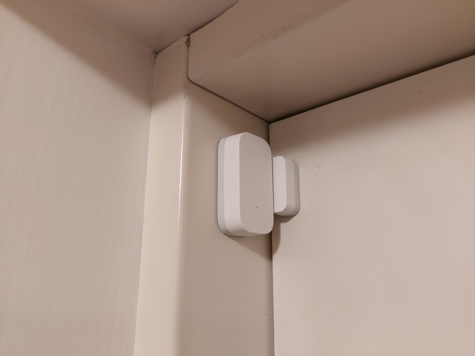
For door and window sensors; I’m using Aqara MCCGQ11LM. It’s small, the battery lasts a long time, and they seem very reliable.
Ideally I’d like wired door sensors, but I don’t see that happening… It’s just not practical to retrofit those with the wires hidden.
I also have a couple of Aqara RTCGQ11LM motion sensors — but those I use mainly as temporary sensors until I can get proper wired PIR sensors installed 😎
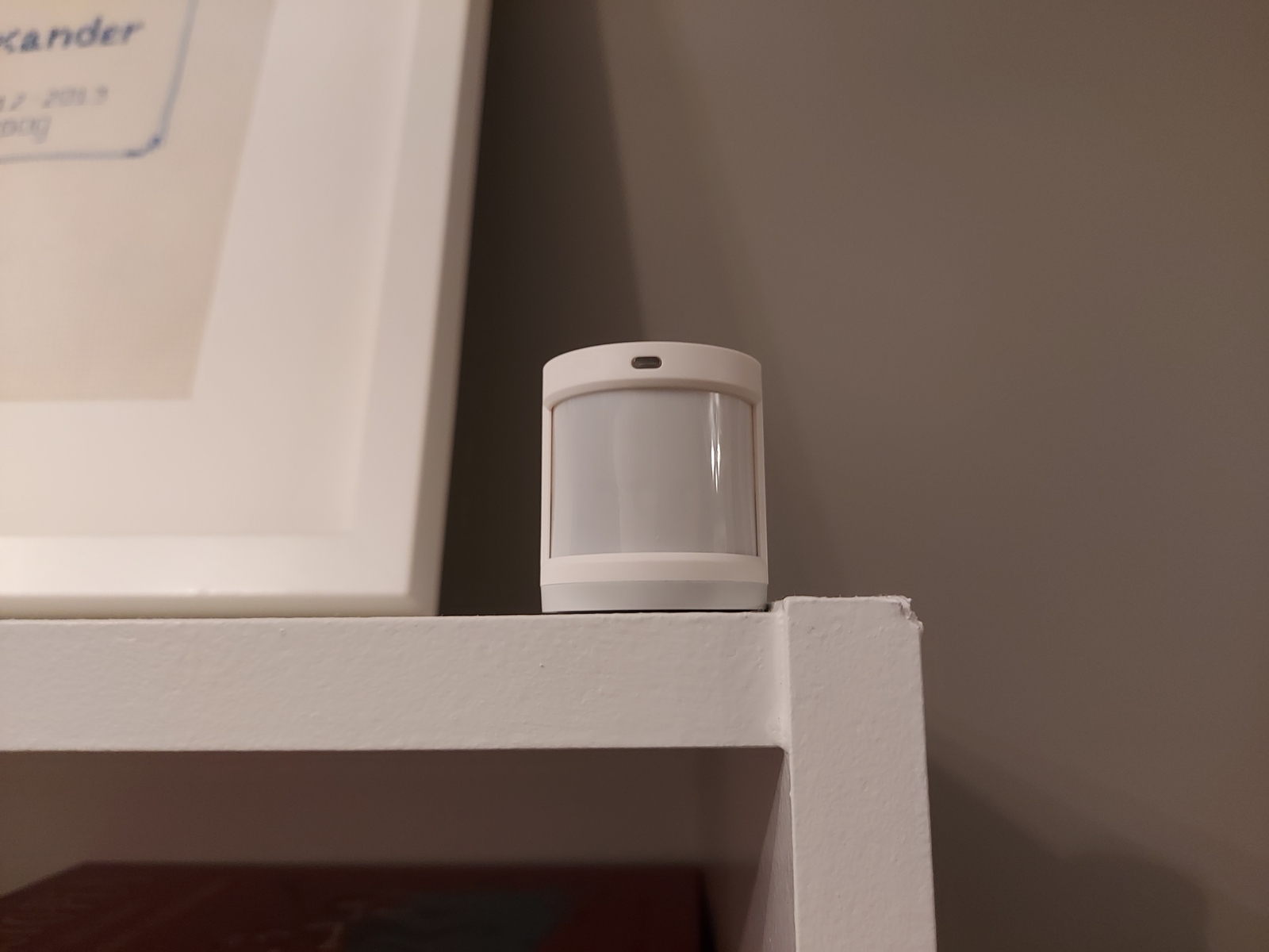
I already had a Philips Hue indoor motion sensor in the entryway — to control the lights, so I figured I might as well include it in the alarm system.
Since my Hue devices are on a separate Zigbee network — I’m relying on the Home Assistant MQTT statestream to forward messages.

Wired hardware
Indoor and outdoor sirens are wired, although I haven’t installed the outdoor siren yet — that’s a job for warmer weather 🙂

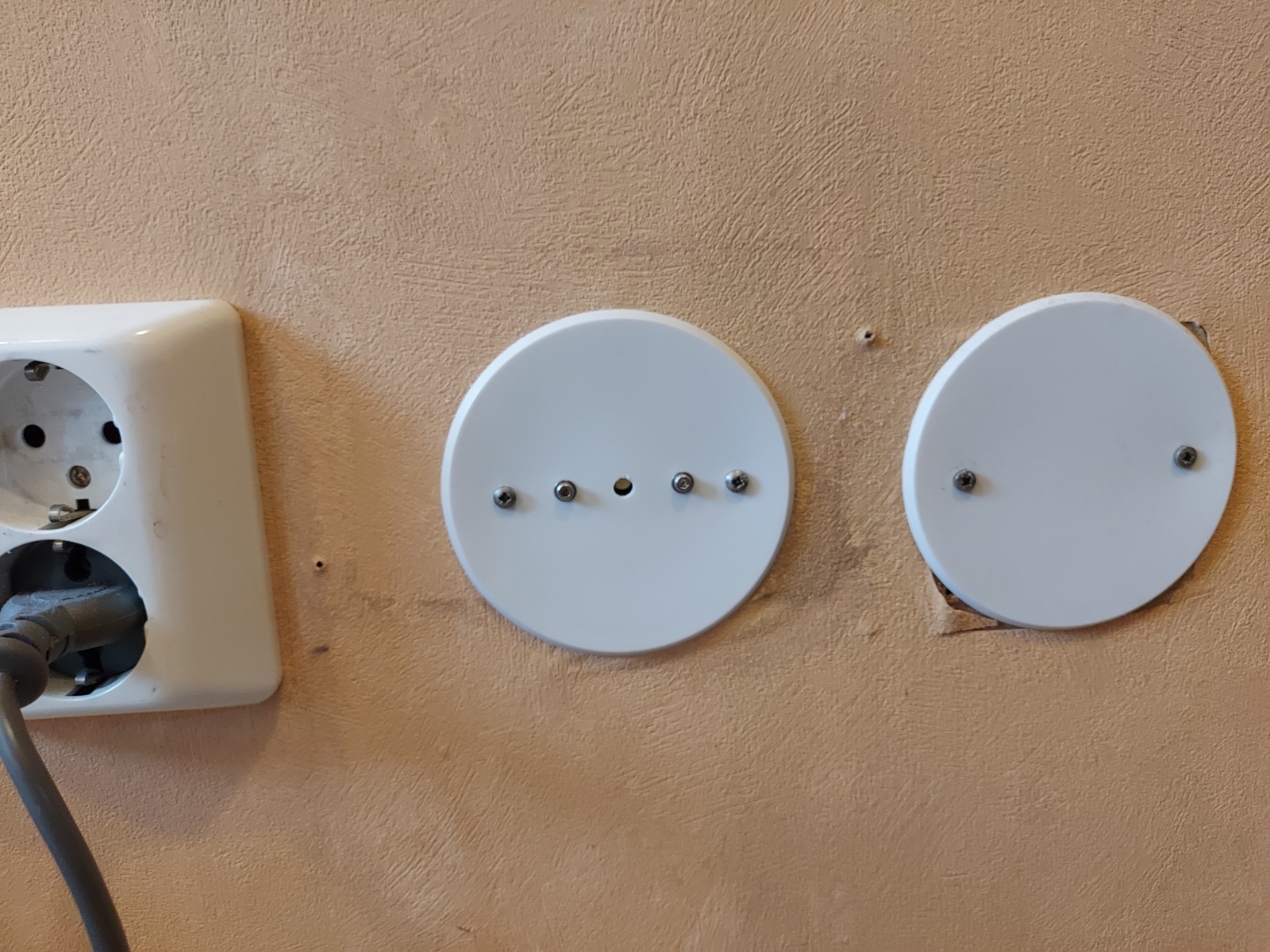
I’ve installed a buzzer in the entryway — utilizing an empty wall box. It’s used to signal entry and exit delay, alarm state changes, door open warnings, and more.
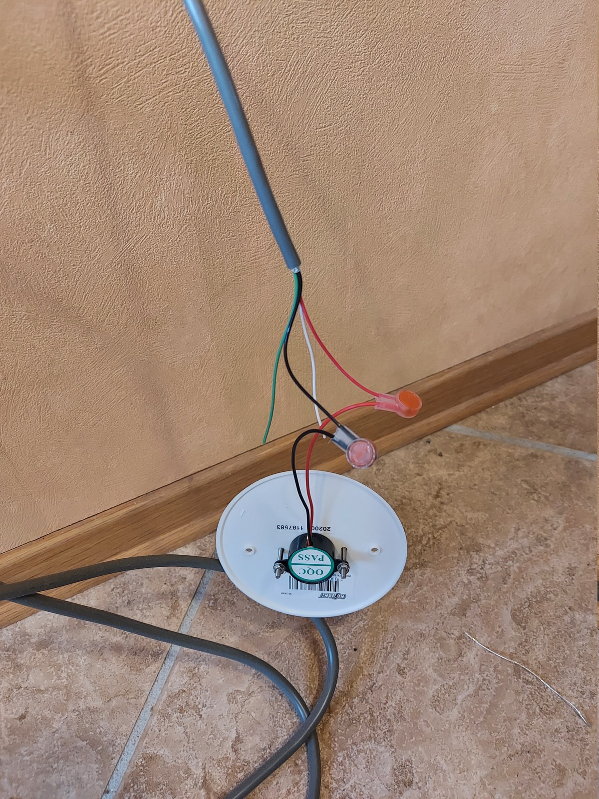
The buzzer is mounted to a wall box blanking plate — making it flush mounted buzzer, and almost invisible 🙂
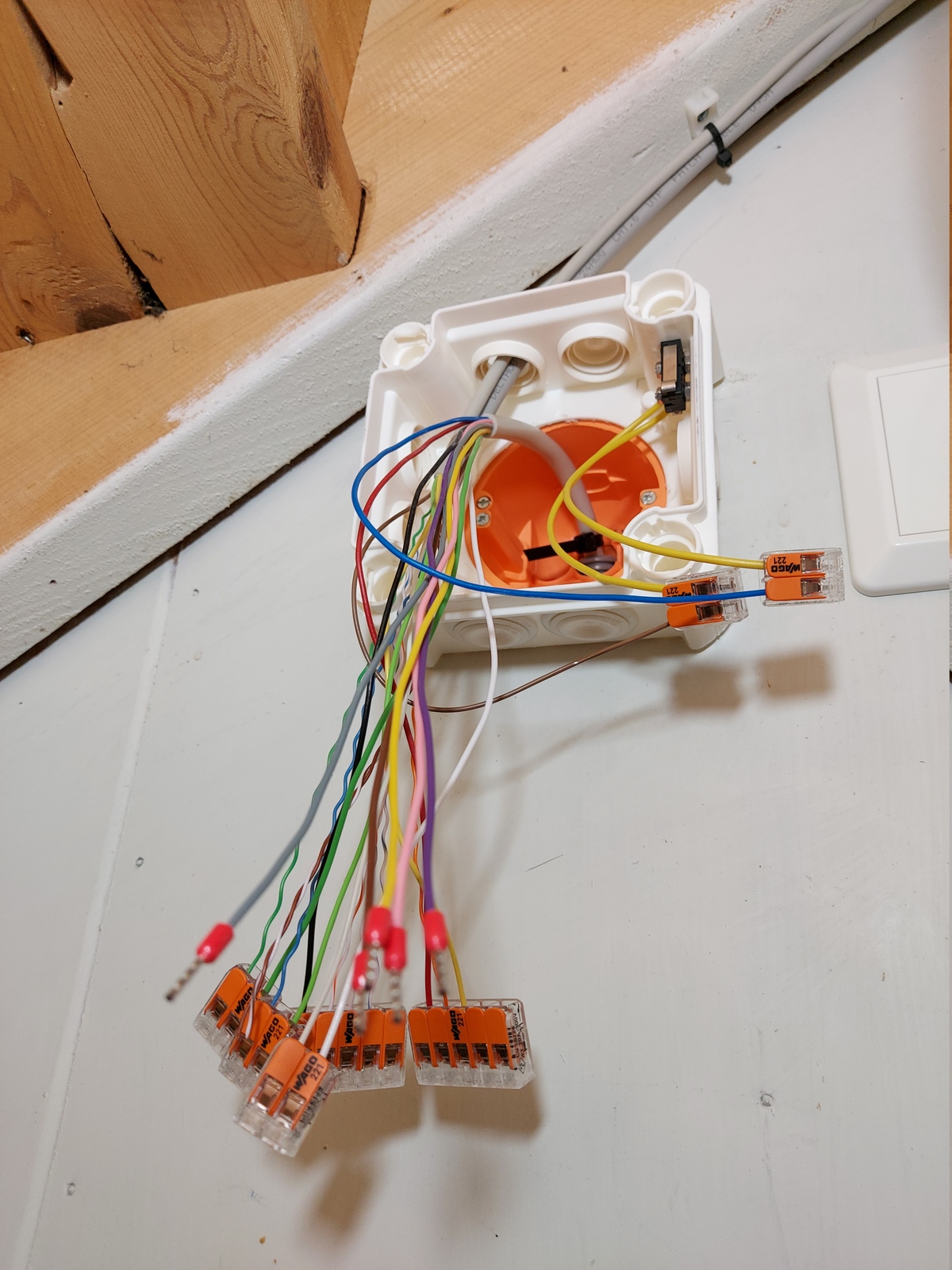
A 10-cores 0.34mm² (22 AWG) signal cable in a conduit — going into a junction box close to some wired devices. The junction box has a tamper switch — detecting if the lid is removed.
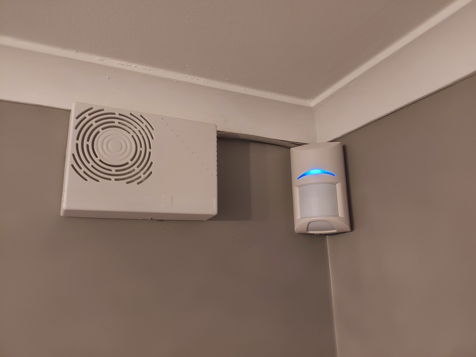
Indoor siren SP203 from Vanderbilt, and Bosch Blue Line Gen2 PIR motion sensor in the 1st floor hallway. I don’t think cables should be visible, so I go to great lengths to hide them. Hidden cables also means they are harder to tamper with 🙂
Software
The alarm application/script is written in Python — I like Python, and there are lots of libraries available for the Raspberry Pi GPIO pins, MQTT, serial port, and more.
Python script
- Source code is available in a git repository:
- https://github.com/thomasjsn/rpi-alarm
Configuration
Simple things like MQTT hostname, API tokens, user PIN codes, times, etc — are defined in config.ini. The alarm state is saved when changed, meaning that the system will enter the same state if the application restarts.
More complex configuration is defined as Python objects directly in the application — things like inputs, outputs, sensors, Home Assistant entities, zone timers, and alarm panels.
Some things are just plain hard-coded 😛
MQTT payload
The alarm system sends a single state object — which contains all states. It’s sent when any of the values changes, but at least once every 10 seconds.
{
    "arm_not_ready": false,
    "battery_chrg": false,
    "battery_level": 100,
    "battery_low": false,
    "battery_voltage": 12.74,
    "clear": true,
    "code_attempts": 0,
    "config": {
        "walk_test": false
    },
    "fault": false,
    "mains_power_ok": true,
    "state": "disarmed",
    "tamper": false,
    "temperature": 21.1,
    "triggered": {
        "timestamp": null,
        "zone": null
    },
    "zigbee_bridge": true,
    "zone_timers": {
        "hallway_motion": true,
        "kitchen_motion": true
    },
    "zones": {
        "door1": false,
        "door2": false,
        "door3": false,
        "emergency": false,
        "ext_tamper": false,
        "motion1": false,
        "motion2": false,
        "motion3": false,
        "panel_tamper": false,
        "panic": false,
        "water_leak1": false,
        "zone01": false
    }
}
MQTT broker
The Raspberry Pi runs it’s own Mosquitto MQTT broker, which the Python application connects to. This is to minimize the dependence on external services.
My main MQTT broker connects to the Raspberry Pi as a bridge — receiving all messages, and passing on what is relevant for the alarm system.
connection rpi-alarm
address 192.168.1.190:1883

topic # in 0
topic zigbee2mqtt/# out 0
topic home/alarm_test/# out 0
topic homelab/src_status out 0
Home Assistant
No configuration is required in Home Assistant; the alarm system will automatically be created as a device, using MQTT discovery.
All zones, zones timers, and alarm panels are automatically published — but any property included in the state object can be published as well, by defining it as an entity.
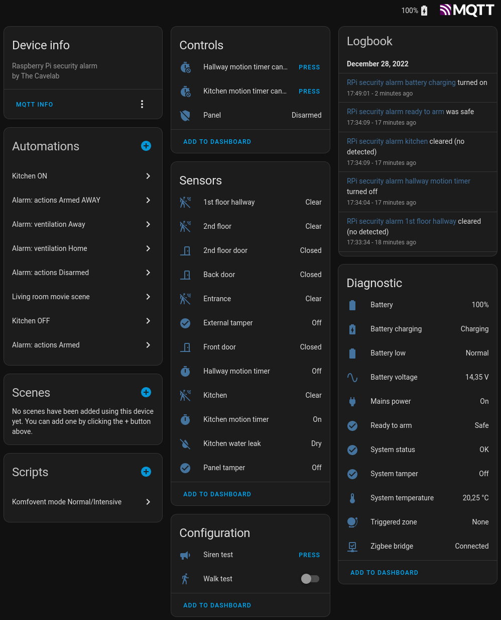
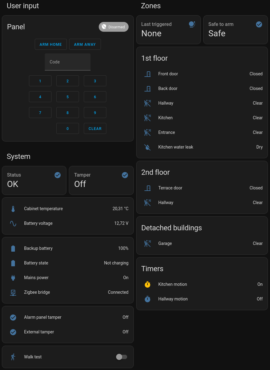
This is my security dashboard — it gives an overview of all sensors and features, as well as some system diagnostics.
Ending thoughts
I’m delighted to finally have this blog post done — it has felt insurmountable. The project has been going on for more than a year, and I’m still adding features and making adjustments.
There’s a lot happening and much of the logic is fairly complex and difficult to explain in detail — I feel like I have barely scratched the surface in this post.
I will be writing more in-depth blog posts in the future, as well as keep you updated as the project progresses 👷
This project is incredibly rewarding, and provides useful features in our daily lives 🙂 I’m currently planning a big feature upgrade for water sensors and actions related to that. More on that later.
🖖
Last commit 2023-12-25, with message: replace emoji slight_smile/slightly_smiling_face
DIY Security Alarm series
- Making a manual security alarm in Home Assistant
- Raspberry Pi security alarm — the basics