This post is part of the Rack box project series.
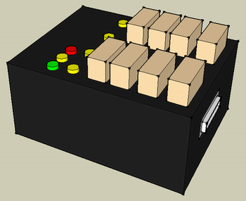
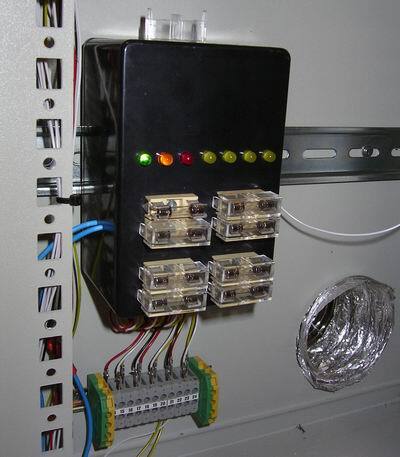
A monitored fuse box that used to be installed in my rack box project, with 4 channels and 8 fuses.
Details
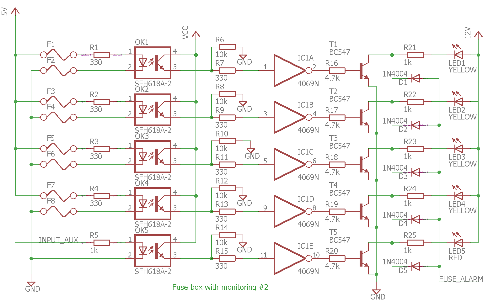
This fuse box module used to be installed in my rack box project. It had a total of 4 channels, or outputs, each with fuses on both polarities. All fuses were monitored, meaning that if a fuse broke; a failure LED would turn on and a fuse failed output activate.
Each pair of fuses powered an optocoupler, which again were connected to an inverter. So if any of the fuses broke the optocoupler would loose power, meaning that the inverter input would go LOW, and the inverter output HIGH.
Each inverter output was connected to a failure LED and a OR gate, which was used to alert another monitoring module of a failed fuse. So the failure LED would indicate which circuit was broken, and the fuse failed output signal just meant that one or more circuits were broken.
So, in summary; this is what happened when a fuse broke:
- Fuse breaks
- Optocoupler looses power
- Signal to inverter is lost
- Inverter output turns on
- Failure LED for that channel lights up
- Fuse failure output is activated, alerting other monitoring modules
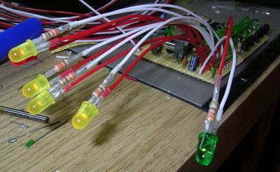
Fuse failure LED
The top-most yellow LED would blink in the case of a fuse failure, regardless of where that failure was. The LED was controlled by another monitoring module, and shared between multiple modules.
Caveats
The solution worked just fine for loads like light bulbs, LEDs etc. But turned out to be a bit strange if electronics were connected, like a microcontroller. The current would find ways to leak through the connected module and back into the output of the fuse box. Which meant that the alarm would turn off. One way to remedy this is to place a diode in series with the outputs from the fuse box, but this introduces a voltage drop.
In my setup I had multiple voltage levels, from multiple power supplies. All their ground terminals where connected together, so I had one common ground. By having fuses on the ground supply I introduced a way that this common ground could break. And that produced some pretty strange results, like microcontrollers powered themselves from low inputs.
Lastly; it’s a complex and time consuming solution to solve a pretty simple task.
So after some testing I decided that it was better, easier, and maybe even safer, to put small fuses inside the modules I was building. I did keep the main fuses for each power supply, those are important.
Video
D-Sub 25-pin
- 5V fuse 1 +
- 5V fuse 1 -
- 5V fuse 2 +
- 5V fuse 2 -
- 5V fuse 3 +
- 5V fuse 3 -
- 5V fuse 4 +
- 5V fuse 4 -
- From LED power supply
- Alarm signal to Main monitoring unit
- Signal from external fuse
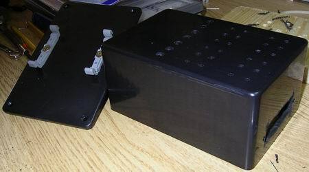
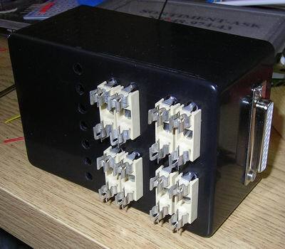
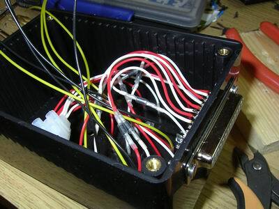
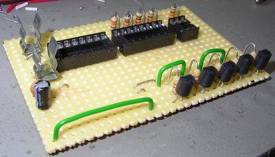
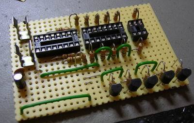
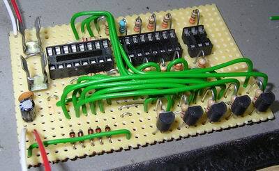
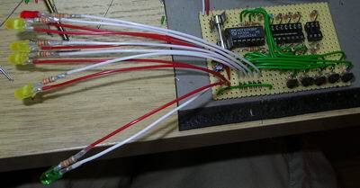
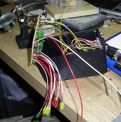
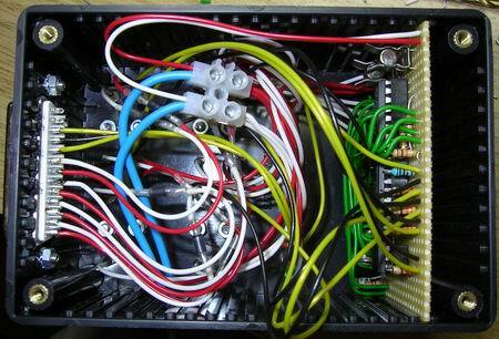
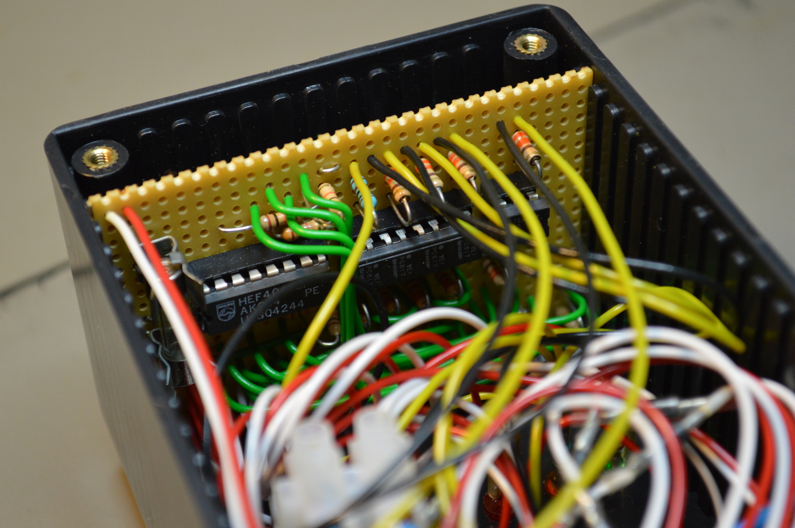
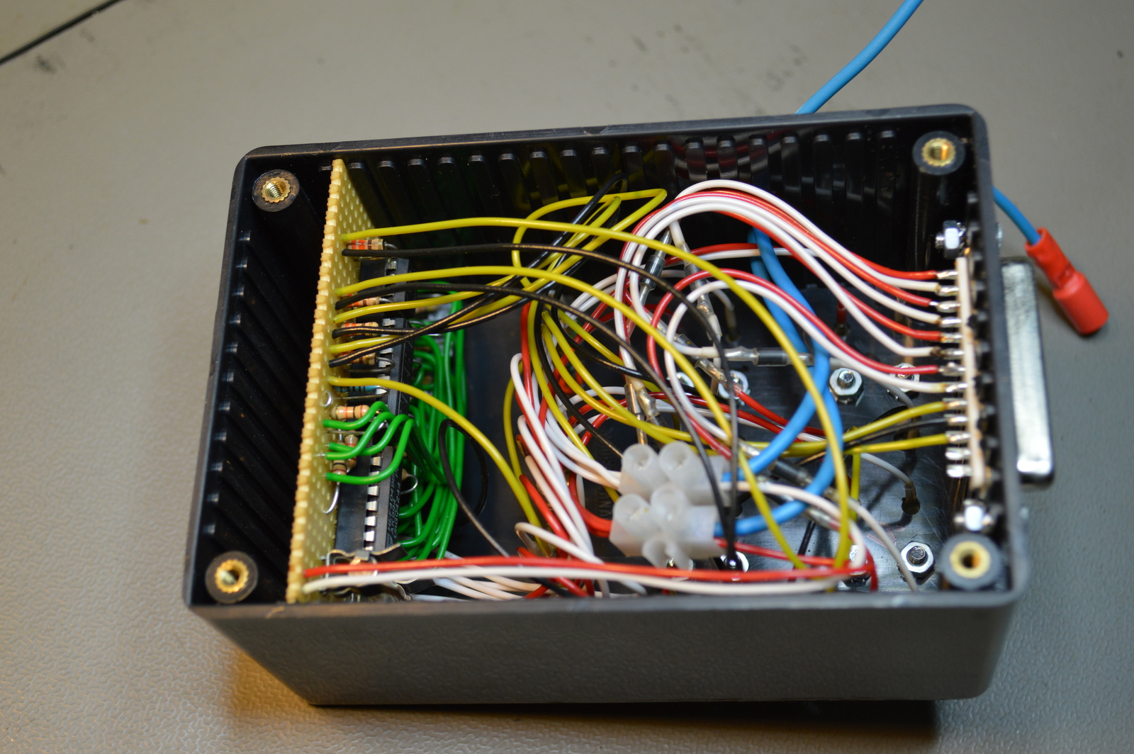
Photos
Schematic drawing
Parts list
- 1 × Capacitor, aluminium electrolytic, 10 µF, 25V
- 1 × Capacitor, ceramic, 1 nF, 100V
- 1 × D-sub soldering cups, 25 pin female
- 2 × DIL socket, 16-pin, 7.62mm
- 1 × DIL socket, 6-pin, 7.62mm
- 8 × Diode, rectifier, 1 A, 400V, 1N4004
- 5 × Diode, small signal, 1N4148/Ph
- 1 × Enclosure, plastic (1591), 120x80x59mm
- 1 × Fuse 5x20 mm, 315 mA, time-delay
- 9 × Fuse holder, open, PCB, 5x20mm
- 8 × Fuse holder, open, PCB, Protective cover
- 1 × Hex inverter buffer, 4049, 6 channels, DIL16
- 1 × LED 5mm coloured clear, Green, 2.1V, 20mA, 30mcd, 10°
- 1 × LED 5mm, Orange, 2.0V, 20mA
- 1 × LED 5mm, Red, 2.0V, 20mA
- 4 × LED 5mm, Yellow, 2.0V, 25mA
- 2 × Mounting bracket, DIN rail, Plastic
- 1 × Optocoupler, 4-channels, PC817
- 1 × Optocoupler, single, CNY17F-3, DIL-6
- 32 cm2 PCB, stripboard, 100x160mm, 160cm2
- 15 × Resistor, carbon film, 0.25W, 330 Ω, 5%
- 5 × Resistor, carbon film, 0.25W, 4.7 kΩ, 5%
- 6 × Resistor, carbon film, 0.25W, 10 kΩ, 5%
- 2 × Resistor, metal film, 0.6W, 1 kΩ, 1%
- 2 × Terminal block, screw, 2.5 mm
- 5 × Transistor, NPN, 100 mA, 45V, 0.5W, BC547B
Last commit 2024-11-11, with message: Add lots of tags to posts.
All posts in Rack box project series
- Parallel port I/O module
- Power supply and fuse monitoring module, AVR
- Monitored fuse box, 6 channels
- Stack lights and horn controller — with AVR
- Mute and light controller for the Rack box — AVR module
- Monitored fuse box, 4 channels
- Module heartbeat monitor, 6 inputs — AVR
- Controller for lights and relays — AVR driven
- Emergency power off controller — controlled by 555 timers
- Fan controller with LCD — AVR powered
- Sound alarm control unit — AVR module
- Multiplexer output extender
- Multi-purpose AVR module
- Electric heater and timer controller — AVR
- Module heartbeat monitor, 15 inputs — LCD and AVR
- Serial port I/O module with 11 inputs — AVR
- Serial port I/O module with 9 in and outputs — AVR
- Serial interface for emergency power off — AVR
- Status panel for the Rack box project
- Intruder alarm system controller — AVR
- Serial port I/O module with 15 inputs — AVR
- Serial interface module, with analog and digital I/O — AVR
- The rack box project — an overview