I’ve got a tiny computer lab at home; a 29U rack with servers, UPS, ATS, PDU, 10 Gbit networking, OPNsense, and all the cool stuff.
The homelab rack sits in my home office, just left of me as I type this text. Because it’s so close I’ve paid attention to keeping the noise as low as possible; I’ve tried buying second-hand servers, but they are just too loud. So I built the computers myself instead, focusing on keeping them quiet.
Table of contents

Introduction
I like Linux, so all my computers run Linux; servers are Ubuntu, desktop and laptops are Arch. I run all my services virtualized with either KVM or LXC, and back up the images and configurations to my file server and the cloud every night. So if anything breaks or I have to take a server down for maintenance, it’s easy to move the guest OS or container to another machine. For that reason, I try to keep network settings the same on the servers; bridges and such.
Top to bottom
Front
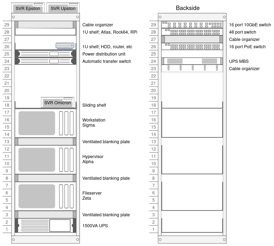
- Top of the rack
- Dell Optiplex 9010 SFF (Hypervisor; Epsilon)
- Dell Optiplex 9010 SFF (Spare; Upsilon)
- 2 × 1U shelves
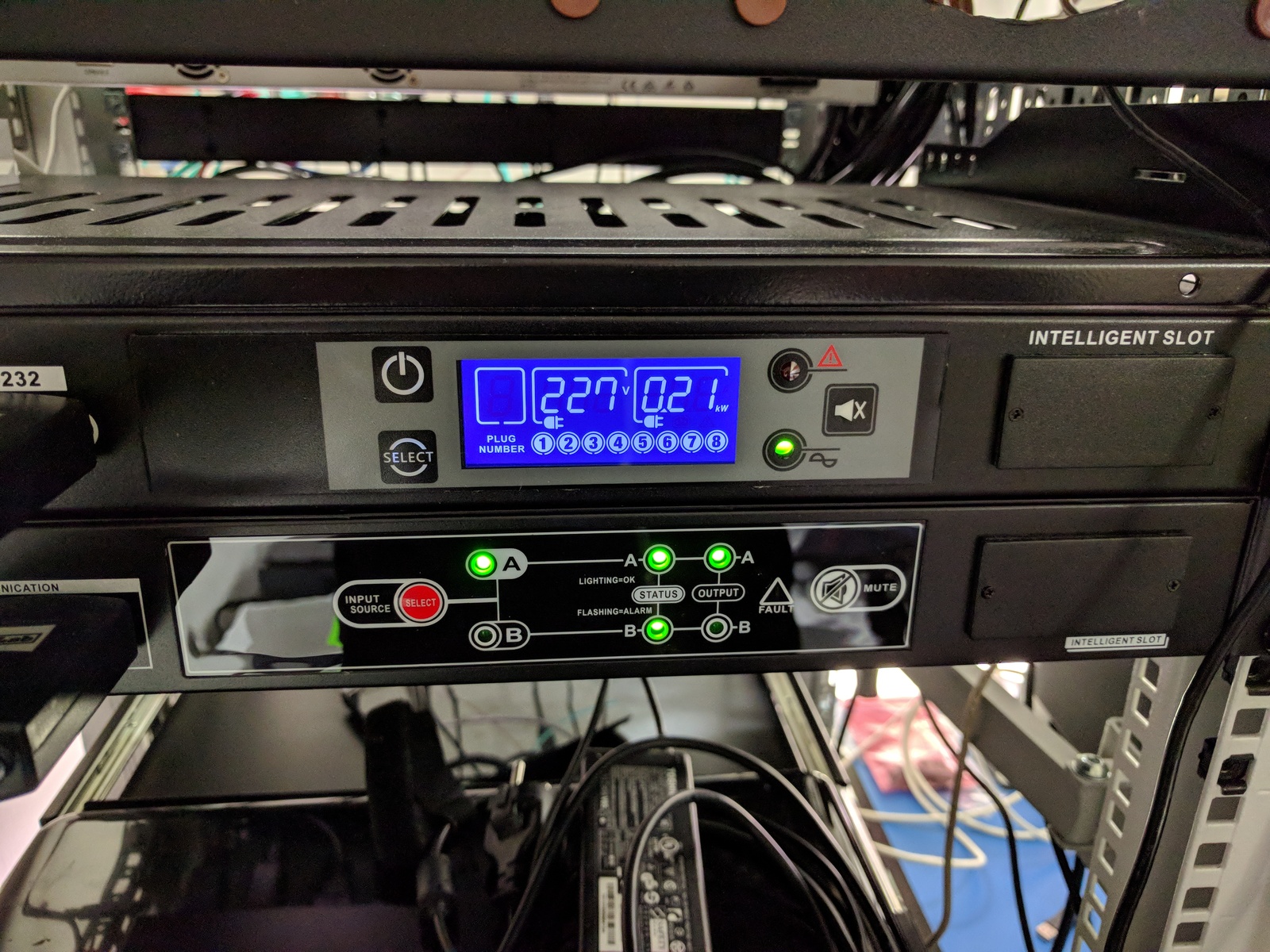
- Power control and distribution
- Power distribution unit; BlueWalker PW PDU RC-16A
- Automatic power transfer switch; BlueWalker PW ATS
- Sliding shelf
- HP EliteDesk 800 G1 USDT (Media server; Omicron)
- Computers, rack-mounted
- UPS; PowerWalker VI 1500 RT HID
Back
- Network equipment
- Power distribution
- Maintenance bypass switch; BlueWalker PW MBS Rack
Computers
Desktops
- Upsilon
- Desktop; Arch Linux, i3 tiling window manager
- Sigma
- Desktop; Arch Linux, i3 tiling window manager
Servers
- Omicron
- Docker host; Ubuntu 20.04
- Epsilon
- Hypervisor; Ubuntu 20.04, KVM+LXC
- Alpha
- Hypervisor; Ubuntu 20.04, KVM+LXC and media server
- Zeta
- File server; Ubuntu 20.04, ZFS
Noise
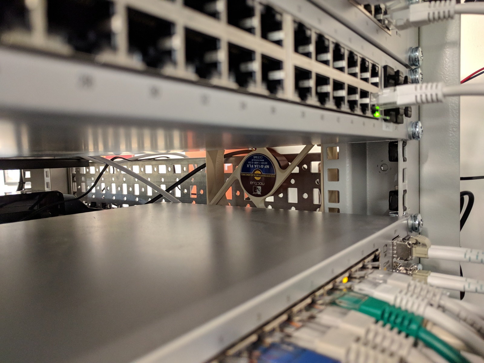
To keep the noise down I only use 4U cases, this allows me to use big (and quiet) fans and CPU coolers. I always replace the stock fans with Noctua silent ones.
I have also mounted a 120mm Noctua fan next to my UniFi US-48 and US‑16‑150W switches, this pushes air through their cases — lowering their temperature enough that their internal fans never turns on. On the 16XG, which doesn’t have temperature controlled fans, I mounted a resistor in series to lower the RPM and noise.
I’ve measured the sound level 1 meter in front of the rack and on the right side, where my desk is located. Measurements were done with the ventilation system turned off, and all computers running.
- 1 meter in front
- 42.1 dBa
- Right side, desk
- 40.7 dBa
Services
- Unifi controller
CCTV serverMirrors(moved to Terrahost)- Home Assistant
Grafana + InfluxDBPrometheus + Alertmanager- MQTT broker
- Plex Media Server
- Gitea
- Drone.io
- Duplicacy backup
Graylog2- Haproxy
- Web servers
- Minio storage
- Matrix homeserver
- Jitsi
- SMTP relay
dnsmasqUnbound (with TLS and adblock)- SSH jump host
- NFS server
- NextCloud
- Miniflux
- linx-server
- MediaWiki
- WireGuard server
- ModSecurity
Network
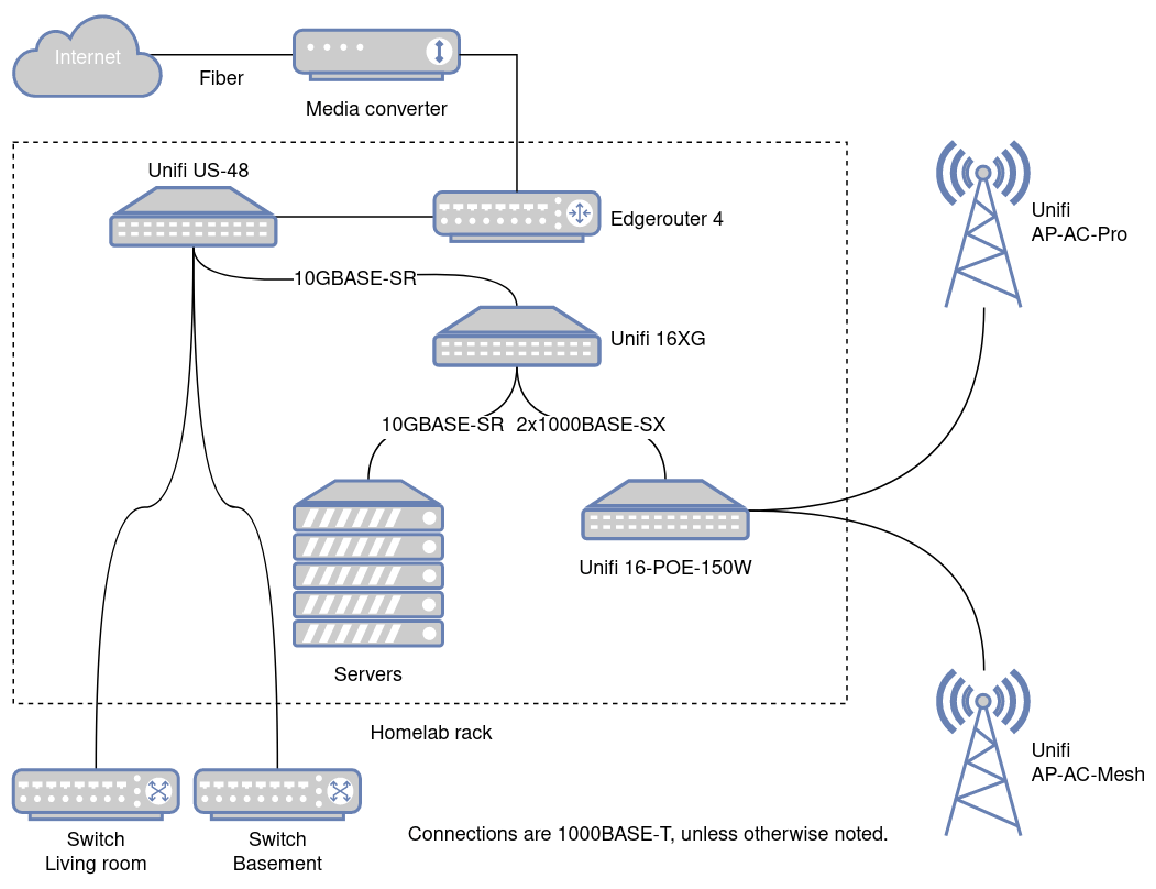
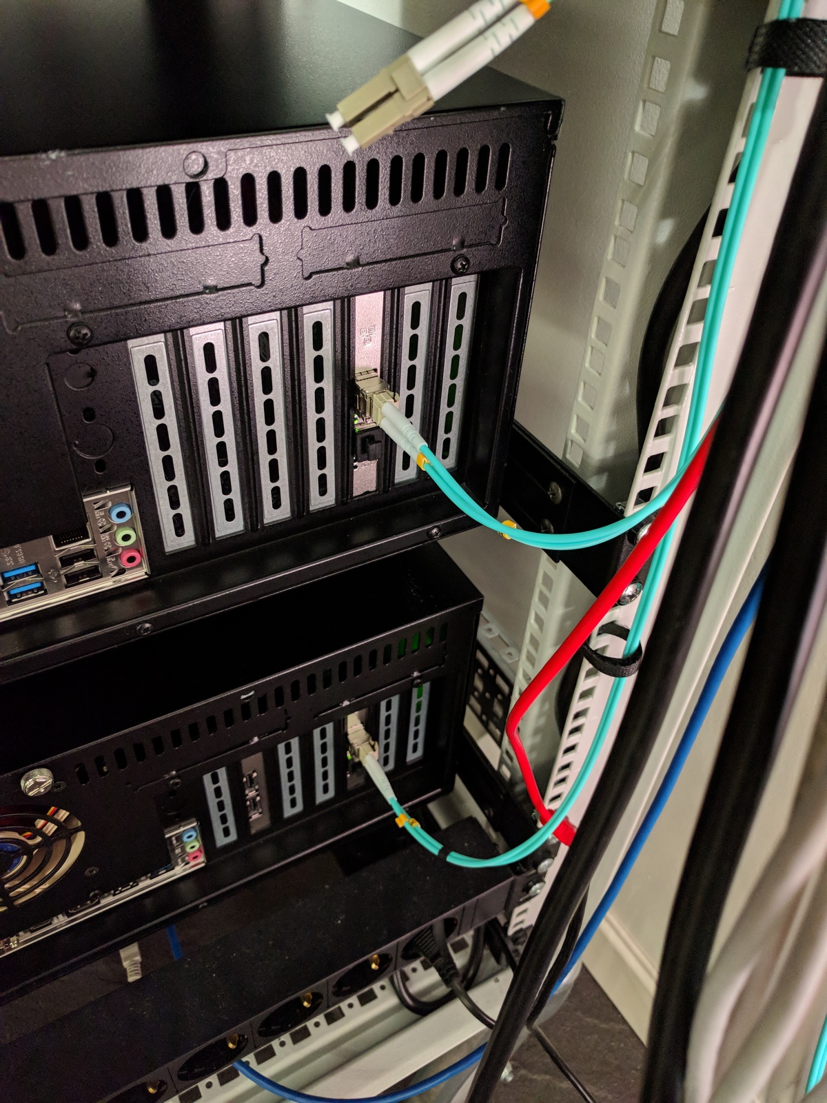
I’ve got a 500/500 fiber internet that comes into the home office and goes through a media converter on the wall above the rack. From there, an Ethernet cable goes to the Edgerouter and to the Unifi 16XG switch, which is the backbone of my home network. All computers in the rack are connected to the network with 10 Gbit multi-mode fiber.
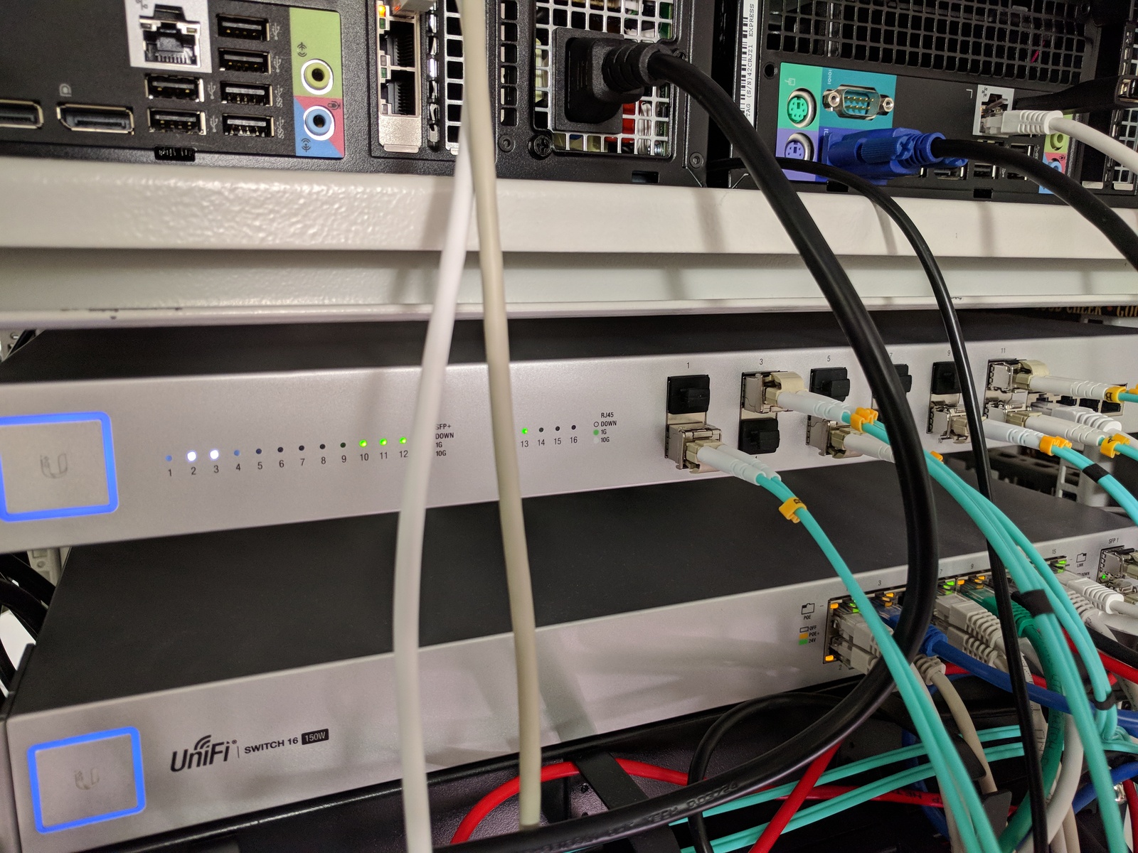
In addition to the UniFi 16XG, I also have a Unifi 16 POE-150W switch, used for Gbit and PoE devices, such as Raspberry Pies and WiFi access points. Between the two switches in the rack are two Gbit aggregated fiber connections. On the wall behind the rack is a 12 port patch panel that connects the rest of the house to the network.
The network is split into multiple VLAN; LAN, DMZ, and CCTV:
- LAN
- This is the default network, and it can access devices in all the other networks.
- DMZ
- The demilitarized-zone, all services accessible from the internet is placed here — things like the NTP server, reverse proxy, SSH jump client and the Atlas probe. It also serves as the wireless guest network. No one trusts each other, and all servers are firewalled. Access to other networks is denied but can be allowed to and from known hosts on specific ports.
- CCTV
- No access is allowed to any of the other networks, accept from the CCTV server. This prevents the cameras from contacting any internet services and provides a bit of extra protection if someone were to connect to the Ethernet cables running outside.
Here is what /etc/network/interfaces looks like on alpha:
# Loopback
auto lo
iface lo inet loopback

# LAN
auto enp6s0f0
iface enp6s0f0 inet manual

# LAN bridge
auto br0
iface br0 inet static
        address 192.168.1.4
        network 192.168.1.0
        netmask 255.255.255.0
        gateway 192.168.1.1
        dns-nameservers 192.168.1.1
        dns-search lan.uctrl.net

        bridge_ports enp6s0f0
        bridge_stp off
        bridge_fd 0
        bridge_maxwait 0

# DMZ VLAN
auto enp6s0f0.10
iface enp6s0f0.10 inet manual
        vlan-raw-device enp6s0f0

# DMZ VLAN bridge
auto br_dmz
iface br_dmz inet manual
        bridge_ports enp6s0f0.10
        bridge_stp off
        bridge_fd 0
        bridge_maxwait 0

# CCTV VLAN
auto enp6s0f0.20
iface enp6s0f0.20 inet manual
        vlan-raw-device enp6s0f0

# CCTV VLAN Bridge
auto br_cctv
iface br_cctv inet manual
        bridge_ports enp6s0f0.20
        bridge_stp off
        bridge_fd 0
        bridge_maxwait 0
As you can see the br_dmz bridge is traffic tagged with VLAN ID 10, and br_cctv with 20. The two VLAN bridges do not have IP addresses, only the virtual networks that use those bridges get IPs.
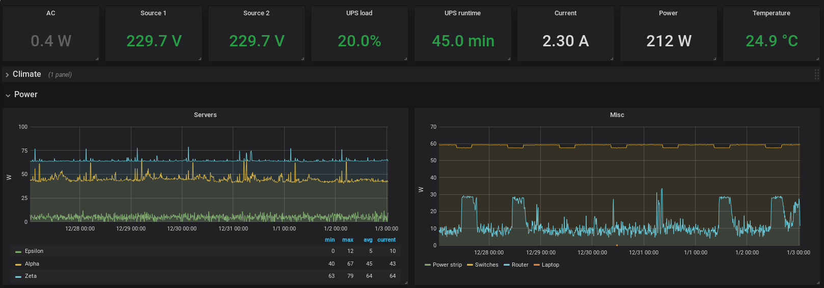
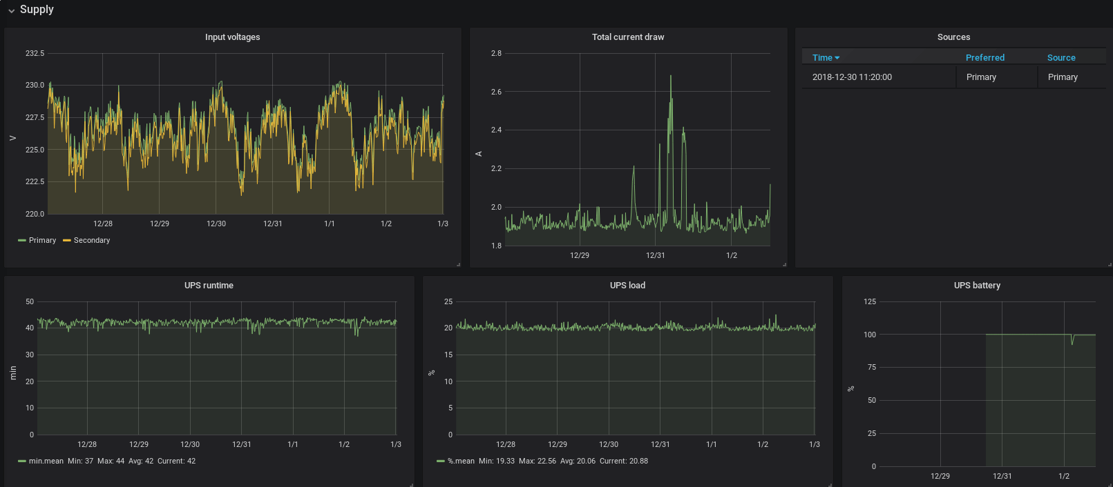
Power
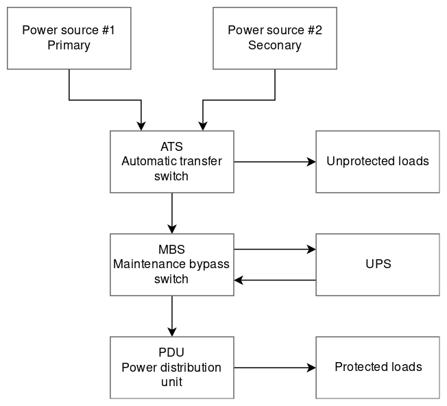
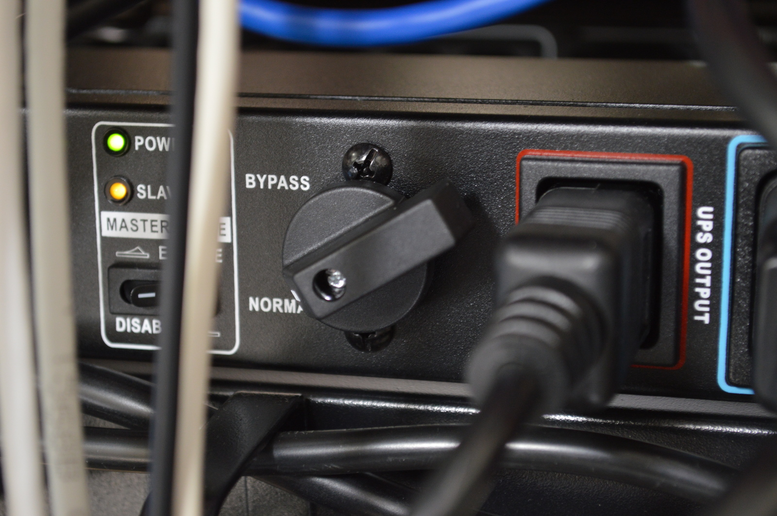
The homelab rack connects to two different branch circuits of the house, through an automatic transfer switch. The primary power source is a dedicated circuit for the home office; the secondary is the basement circuit. The automatic transfer switch, or ATS for short, provides the ability to switch input source if one should fail. This switch typically takes 9 to 12 ms and is transparent to the load.
Any load on the rack that does not require UPS protection is connected directly to the ATS, such as my workstation computer, monitor, laptop charger and a few other things.
The ATS powers the UPS through a maintenance bypass switch (MBS); this allows me to bypass the UPS for maintenance or testing, without turning off any of the connected devices. When the MBS is in bypass mode, the system is without UPS protection.
At the end of the power distribution chain, is the power distribution unit, or PDU for short. The PDU has eight C14 sockets that can be individually controlled and measured.
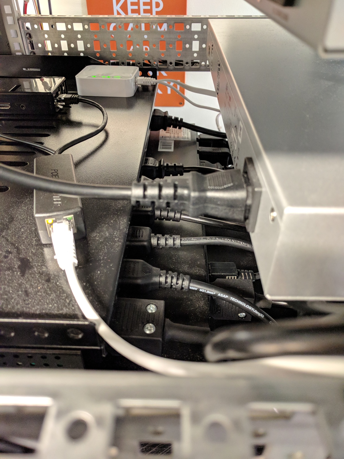
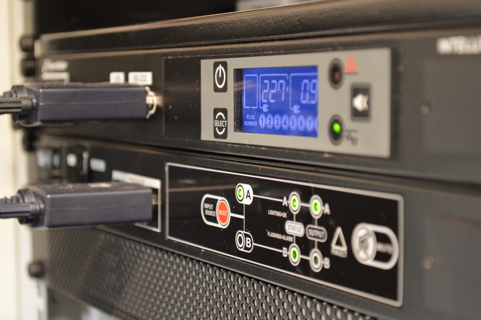
The ATS, UPS, and PDU are all communicating with a Raspberry Pi — that is acting as a power controller and monitor. The UPS has a network management card (NMC) that allows nut to communicate with it over Ethernet. The ATS and PDU are connected via serial port and uses a Python library, that I have written, to communicate.
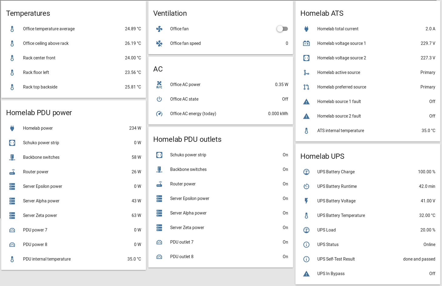
Collected metrics like load, running time, voltage, current, power, and temperatures are read and published as MQTT topics; which Home Assistant subscribes to. The values are also stored in InfluxDB, where they can be read by Grafana to create graphs and cool looking dashboards.
Power loss video
Power walk through video
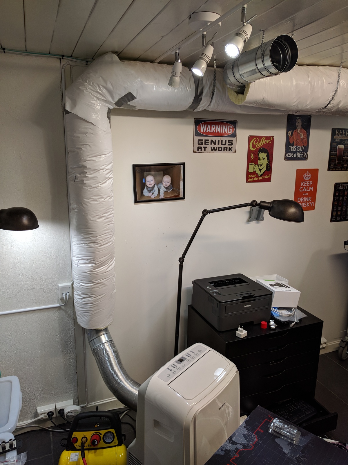
Ventilation
My home office is 10.5 m2 (113 ft2), in the basement and pretty well insulated. With the heat output from the homelab and nowhere for that heat to go, it could potentially get pretty hot. But with my ventilation system, that heat is either vented outside or cooled with a portable AC.
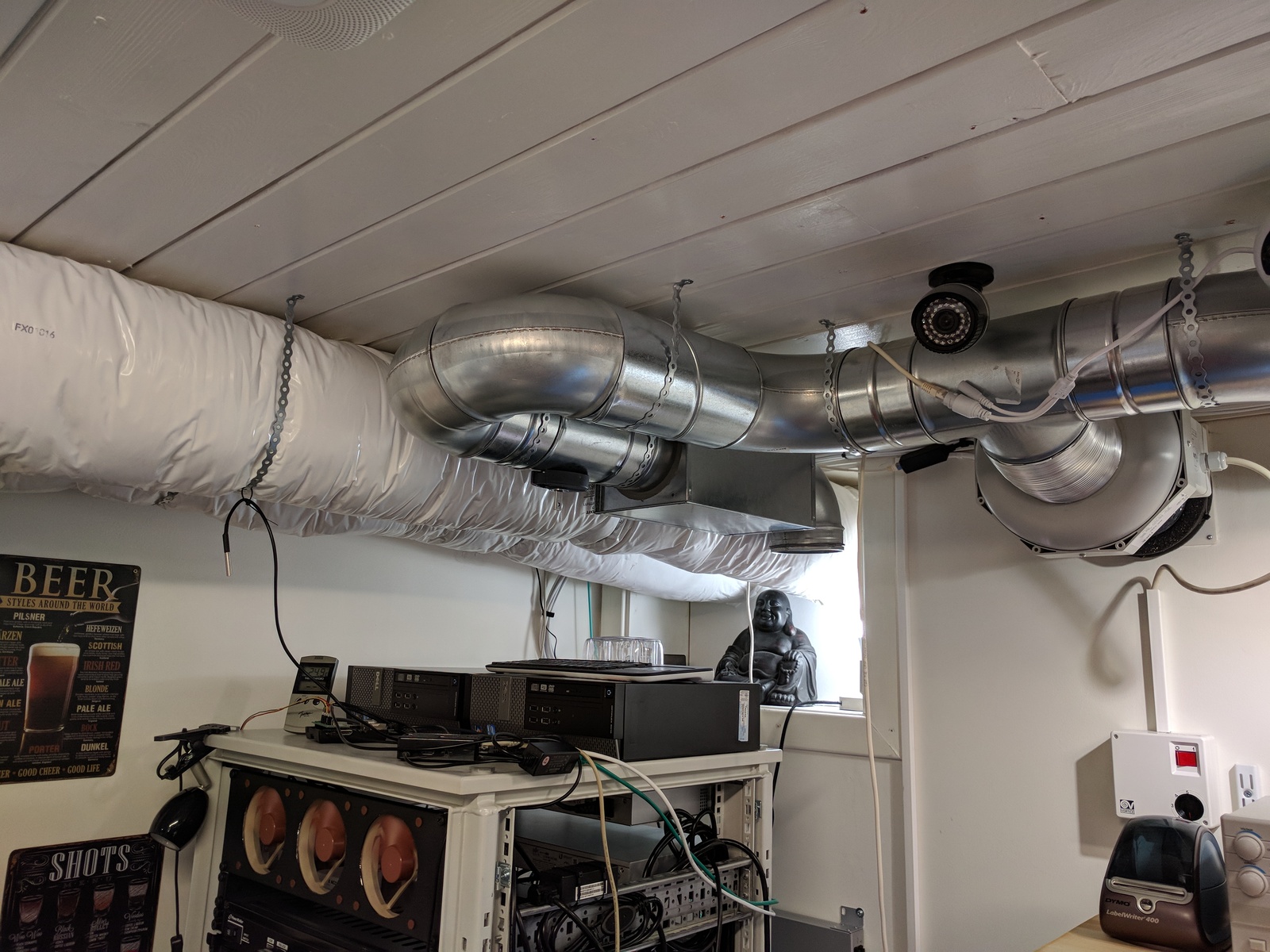
Exhaust
Pulls in air from two places — the ceiling above the rack, and through a fume extraction arm on the electronics lab bench. Both inlets have valves to regulate the flow of air or shut them off completely. The fume extraction on the desk is only open when I solder or do other things that make nasty fumes.
Fresh air inlet
An insulated duct transports fresh air from outside into the center of the room; this is done passively when the exhaust fan is running. It has a valve that can be closed if it’s freezing outside.
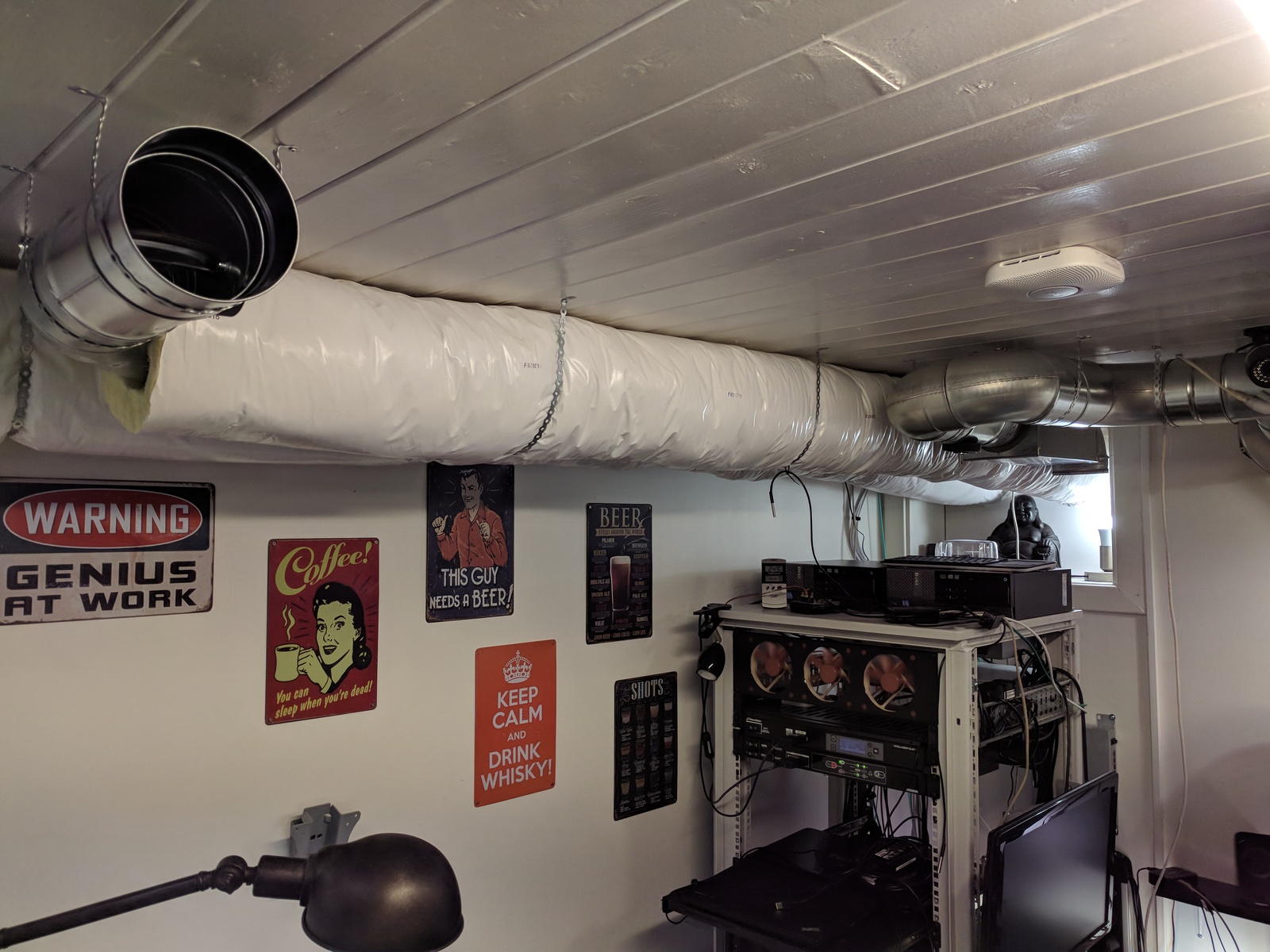
Internal inlet
I have two 100mm (4") inlets coming from the adjacent room, with valves that can be adjusted. I normally keep them closed and pull in outside air. However, in the hot summer months, they can be opened if the basement air is cooler than the outside.

AC
I have a portable AC unit with a dedicated and insulated exhaust duct to outside. When running, it exhausts quite a lot of air. That creates a negative pressure in the room, which pulls fresh air through the inlets.
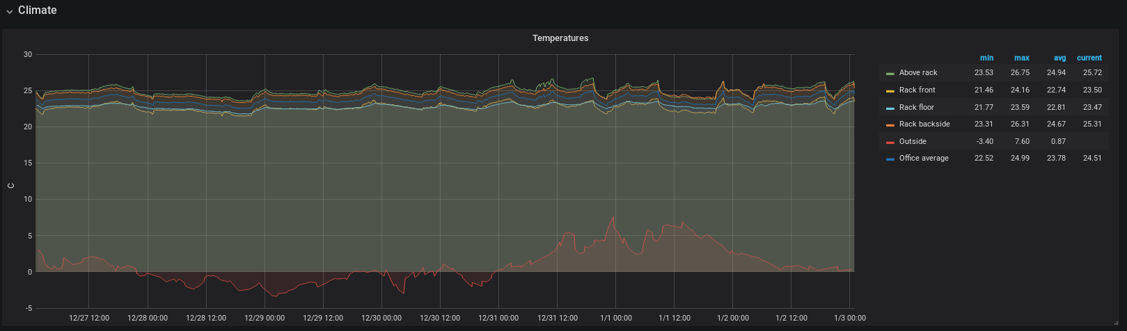
I use a Raspberry Pi, some DS18B20 temperature sensor probes, and a Python script to measure the room temperature. The readings, along with an average, is published as an MQTT topic which Home Assistant subscribes to.
A Home Assistant automation script starts the exhaust fan when the temperature reaches 25’C (77’F). The fan keeps running until the temperature has dropped to 23’C (73.4’C).
Last commit 2024-02-09, with message: Remove links to Omicron and Epsilon in blog posts.