I get emails from readers every now and then — but no topic has caused more interest than the 6-pin fan header on my two Inter-Tech server cases, 4U-4416 and 4U-4129-N.
Perhaps for good reason, it allows for the internal 120 mm fans to be PWM controlled. But is completely undocumented! Let’s have a closer look 😃
Table of contents
Our 6-pin header
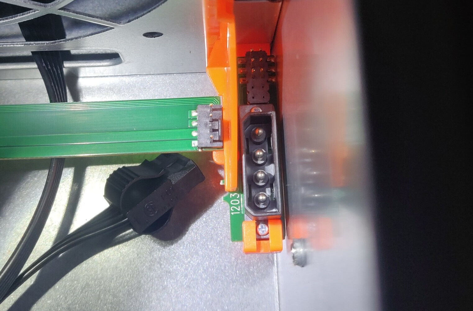
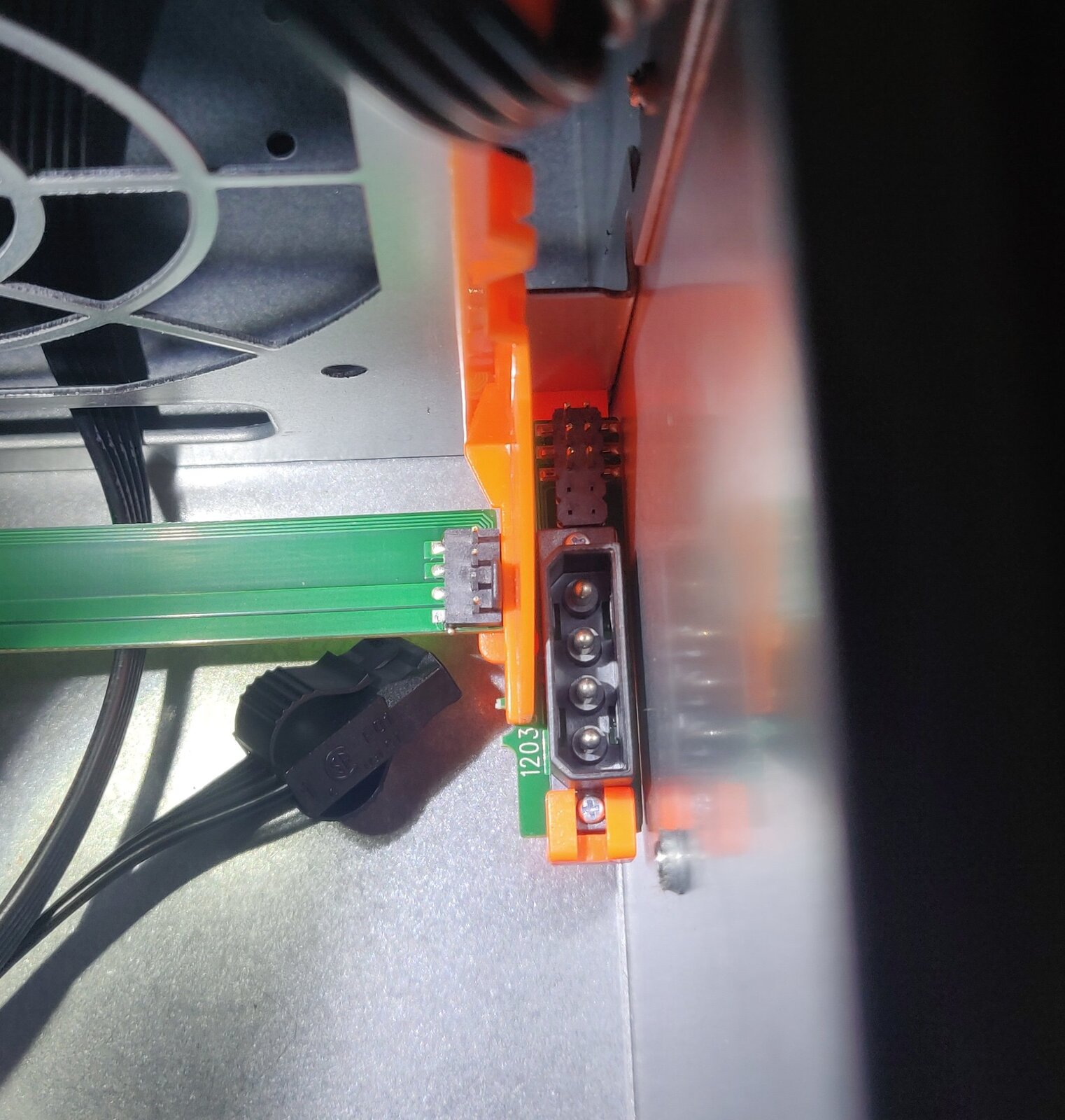
The header is located right next to the molex power connector for the 3×120 mm internal fans.
A reader, Julien Brunet, tested where the pins went and made a pin-out table.
| Fan | Pin row 1 | Pin row 2 |
|---|---|---|
| Furthest | PWM | Tach |
| Center | PWM | Tach |
| Closest | PWM | Tach |
The 4-pin fan header
A standard 4-pin fan header provides the fan with 12V, GND, sense and control.
| Pin | Wire color | Function |
|---|---|---|
| 1 | Black | GND (0V) |
| 2 | Yellow | +12V |
| 3 | Green | Sense/Tach |
| 4 | Blue | Control/PWM |
Using the 6-pin header
There are two ways that we can use this header to control the internal fans: individually and together.
Individual fans
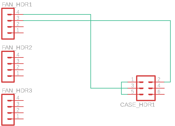
We can connect the PWM and Tach signals for each fan to a 4-pin fan header on the motherboard, or some other fan controller. This will require three fan headers, and allow us to control and read the speed of each fan individually.
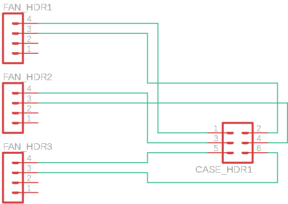
Inter-Tech has apparently made a cable for connecting an 8-pin header to four 4-pin fan headers, supporting four internal fans. It is part of their 120 mm fan set — and this is what it looks like:
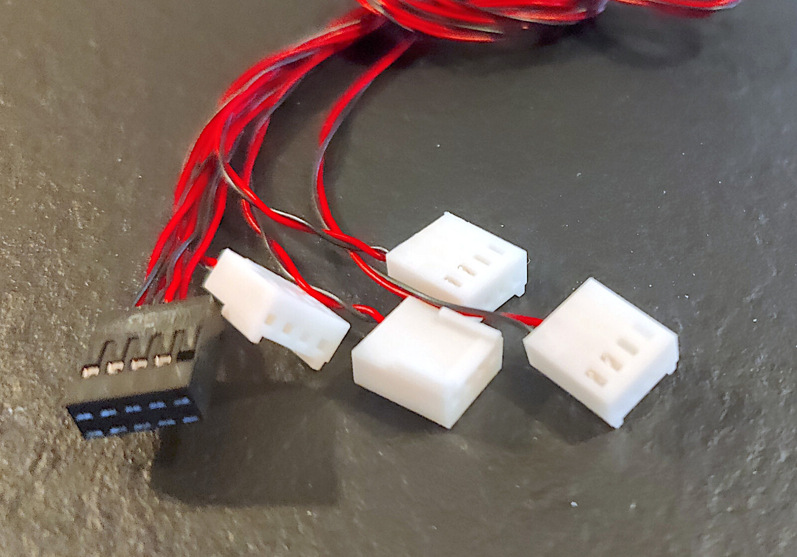
But some jump (DuPont) wires can easily be used instead, just make sure to double check the pin-outs first.
Fans wired together
Another way to control the fans, which will only require a single 4-pin fan header, is to connect the PWM signals together.
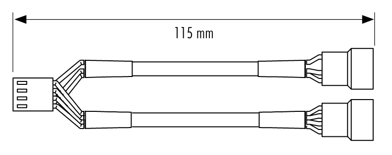
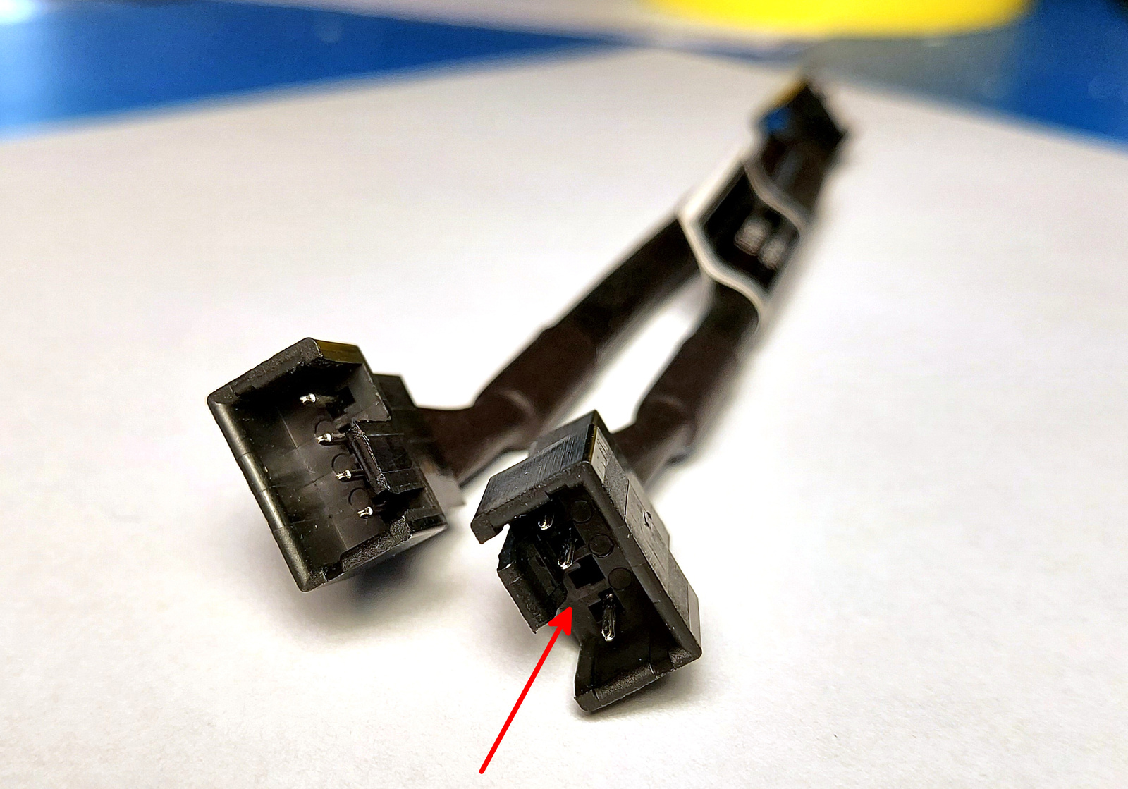
Let’s have a look at a Noctua NA-SYC1 fan splitter — it takes a single 4-pin fan header and turns it into two. Similar to what we are trying to do.
Looking closely at the Noctua Y-cable, we can see that it splits the PWM signal, but not the Tach signal.
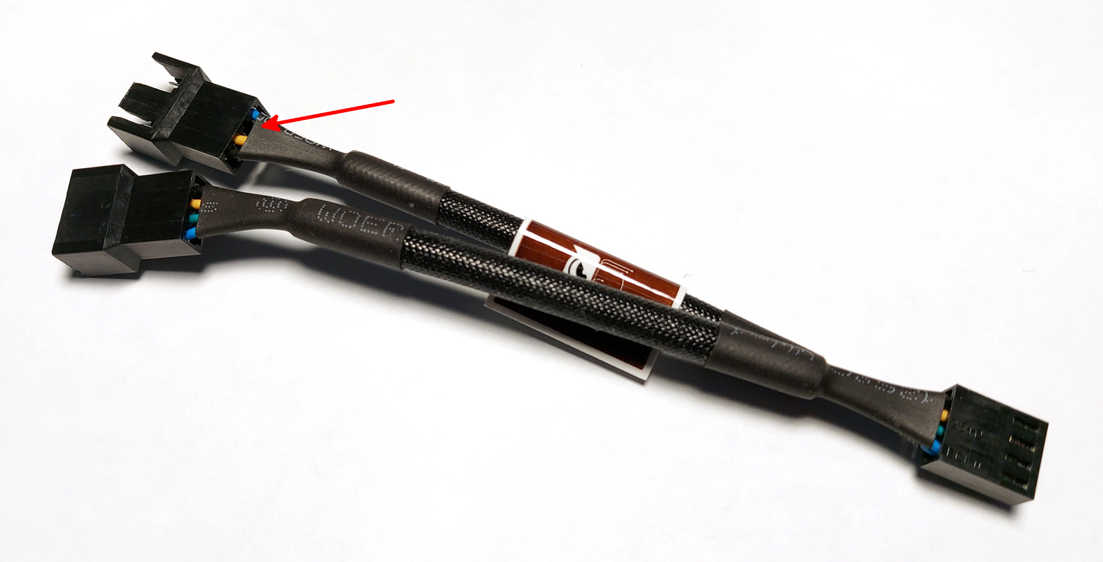
This makes sense, as the PWM is a controlling signal going from the motherboard to the fans. But the Tach is the RPM readout going back — so combining the Tach pins makes no sense.
I suspect you need the Tach signal from a single fan to satisfy the motherboard, or whatever fan controller you are using.
Here we can clearly see that one connector is missing pin 3 — the Tach signal.
Postface
A special thanks to Julien Brunet for helping me figure this connector out 👍
So with this I feel I have done my part in documenting what this header actually does. I hope you found it useful 😃
Last commit 2024-11-11, with message: Add lots of tags to posts.