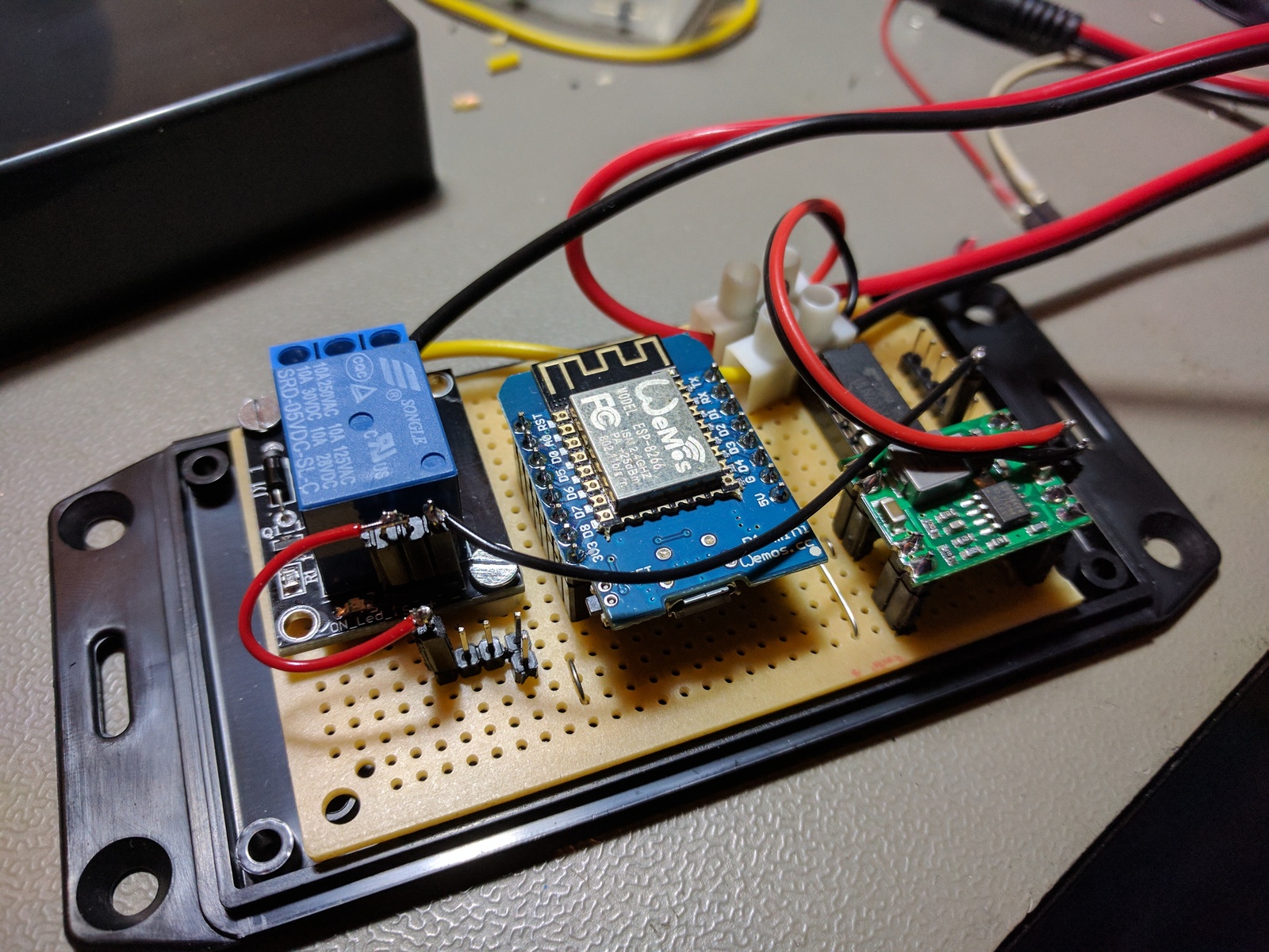
I’ve wanted to use an ESP8266 WiFi module in a project for some time now, and after reading about the WeMos board, I figured this was the easiest way to get started. The WeMos D1 mini is quite small and much easier to interact with and program than the ESP8266 devices. So I built this single relay controller, with internal temperature reporting. I am communicating with it using MQTT, which makes it really easy to implement it into things like Home Assistant.
Table of contents
Details
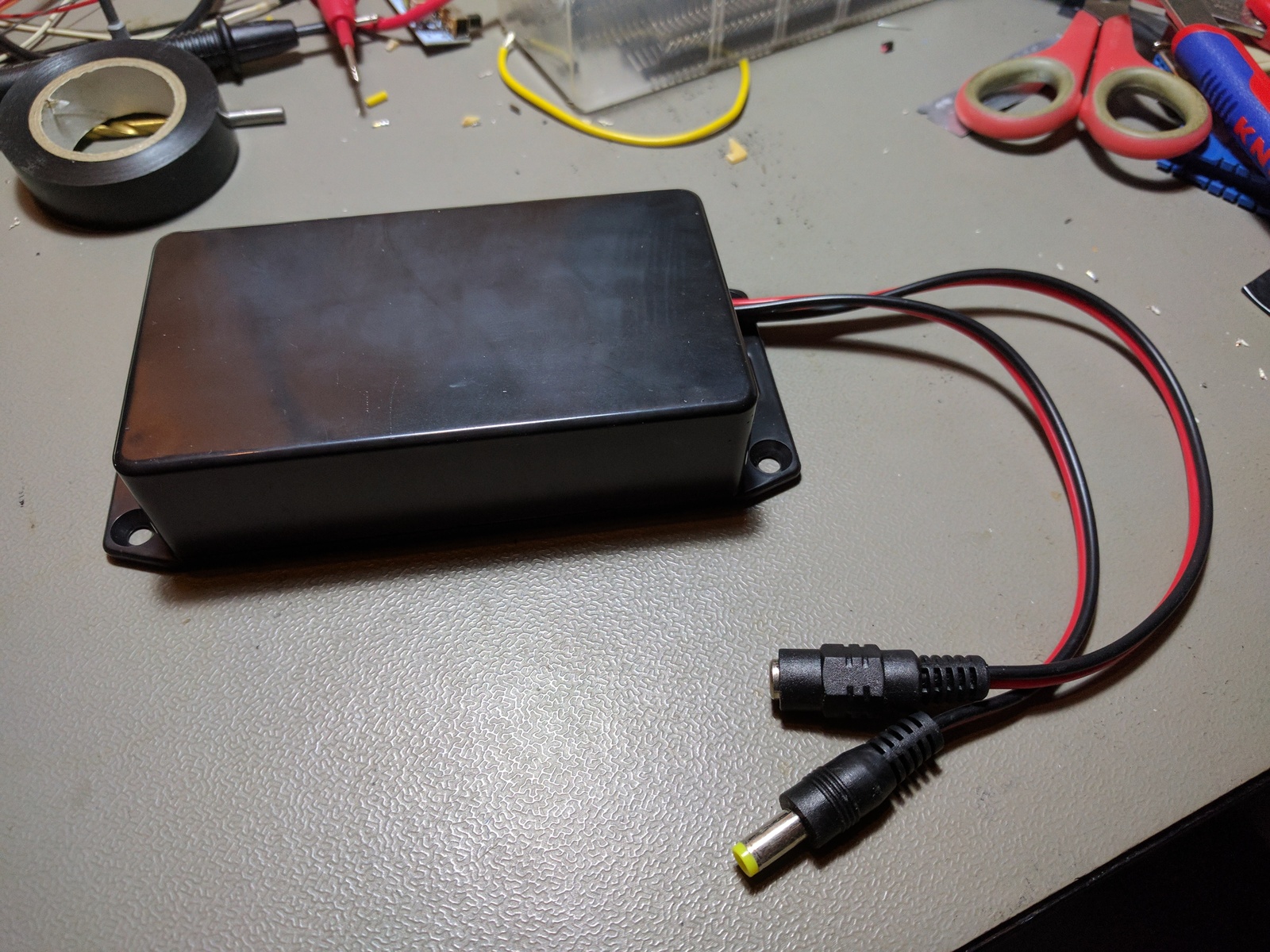
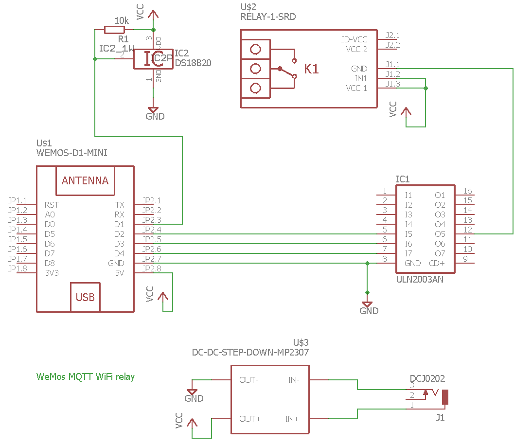
It’s s pretty simple concept, power jack in and power jack out. The input power drives the unit and is passed through the relay and out on the female power jack. So the output voltage is equal to the input voltage.
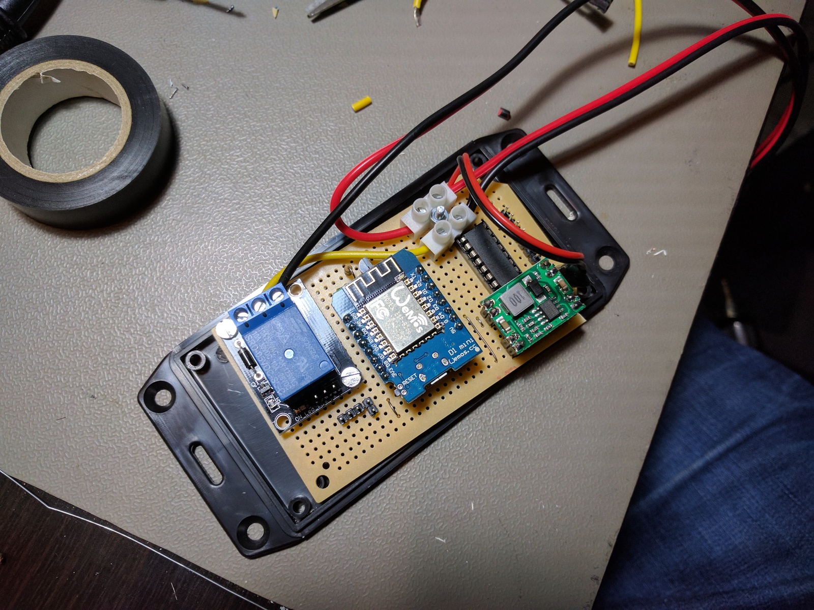
I’m using a buck step down converter to turn the input voltage into 5 V for the WeMos and relay. A step-down converter generates a lot less heat than a voltage regulator, that allows it to supply higher current with no cooling. The one I used here can handle 7 to 28 V input and delivers 3 A.

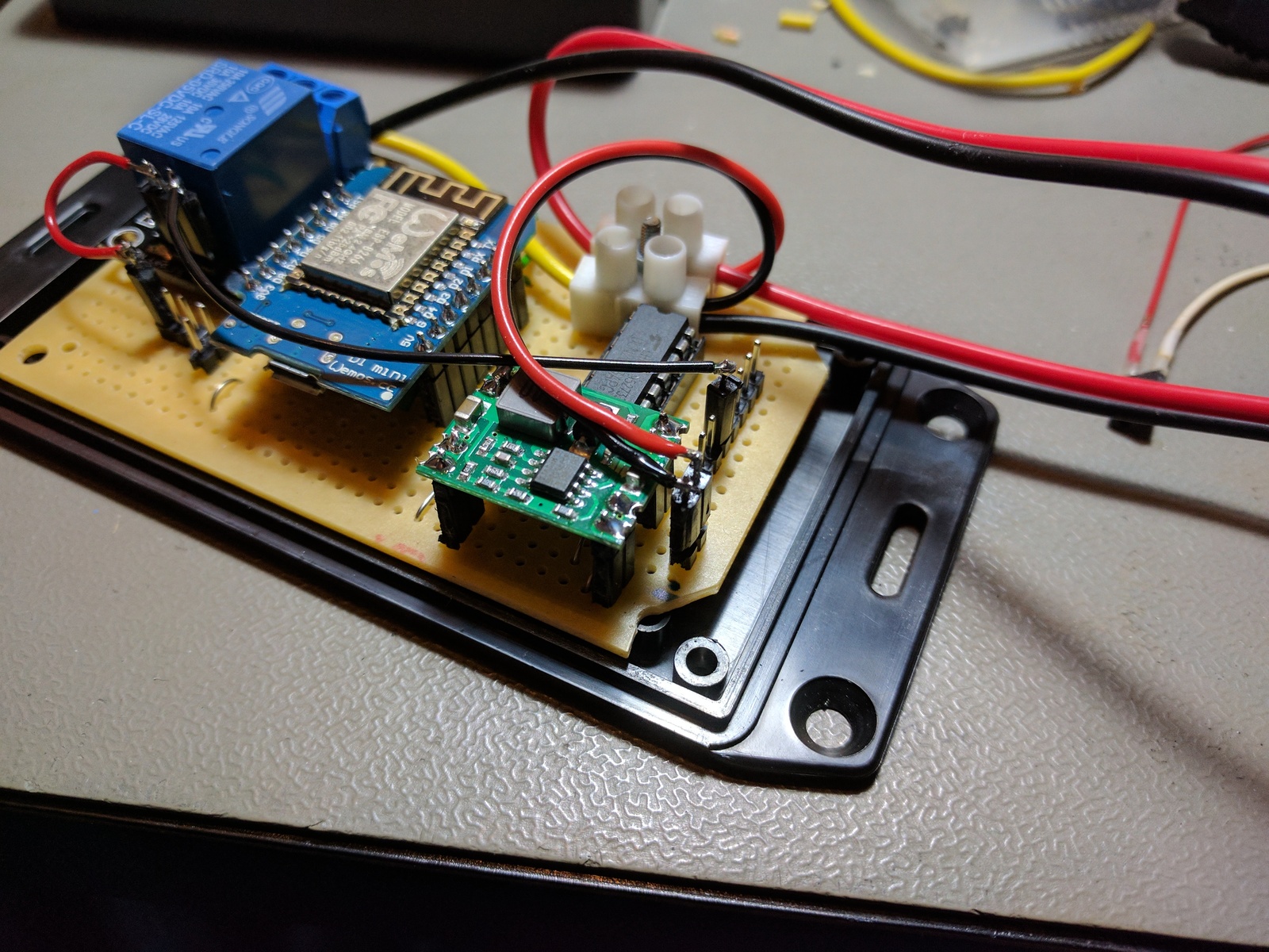
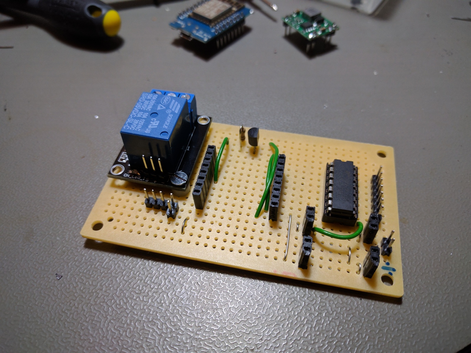
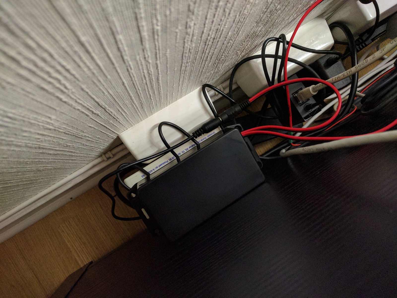
I am currently powering it with 9 V and using it to control the bias lighting behind my TV. Since my TV has an Ethernet connection, I can detect whether the TV is on or off by trying to ping it a few times a minute. And then using a Home Assistant automation, it can be turned on and off automatically. To drive the relay, I am using a Darlington ULN2003A driver, which may not have been required since the relay board I am using apparently has a driver. Oh well.
I also included an internal temperature sensor, a DS18B20. These are pretty accurate and very easy to interact with. I was a bit worried that the internal temperature of the unit would get high, with the step-down converter, WeMos, and relay. I’ve been graphing the temperature using Munin, and this is what it looks like:
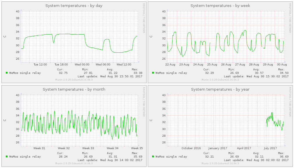
It’s clear that the temperature goes up when the relay is on, but it seems to stabilize at the mid-30s. Munin is a pretty great tool for graphing sensor values; I am working on an article about it.
Software
The Arduino sketch can be found on GitHub.
MQTT
I chose MQTT because it is lightweight as pretty much ideal for IoT devices. It also makes it very easy to interact with the unit from Home Assistant since it has MQTT components. You can see my Home Assistant configuration here. During assembly and for debugging purposes I normally use MQTT.fx.
Topics
I’ve been thinking a lot about how to structure my MQTT topics. Almost every guide I have read on the web uses topics like livingroom/temperature and bedroom/lights/ceiling. That does not seem practical to me. I don’t want to have to reprogram my devices if I ever move them, get more lights or sensors. So I thought it best that the device topics is unrelated to what the device is doing, and instead related to the device itself.
I have, for now, settled on the following MQTT device topic pattern:
# read system temperature
node/qm9/sys/temp

# set relay on or off (0/1 payload)
node/qm9/relay/set

# response sent by device acknowledging relay command
node/qm9/relay
The first and second levels identifies the device itself; node signals that this is a network node, that has a node ID; which is the second level. The node ID is a unique three-letter base36 identifier only used by this device, in this case, qm9. Prefixing with node means that other services can publish without being mistaken for a network node.
The third level is the function; it may be an input or output. sys is a special function used to report device internal system values, like temperature, voltage, battery level, etc.
A fourth level of set is used to send a command requesting a status change in the third level. The device always responds with the same topic, minus the fourth level, to indicate that the command was carried out.
Node IDs
The node IDs are auto-generated by my logistics system, and it also stores associated identifiers, like MAC address, and location. This information is made available through an API, so any service I write can lookup the nodeID to figure out what it is, and where it is placed.
Home Assistant configuration
Define temperature sensor and relay, as light in this example:
sensor:
 - platform: mqtt
   state_topic: 'node/qm9/sys/temp'
   name: 'Internal system temperature'
   unit_of_measurement: '°C'

light:
  - platform: mqtt
    name: "Relay output"
    state_topic: "node/qm9/relay"
    command_topic: "node/qm9/relay/set"
    payload_off: 0
    payload_on: 1
    qos: 1
I/O
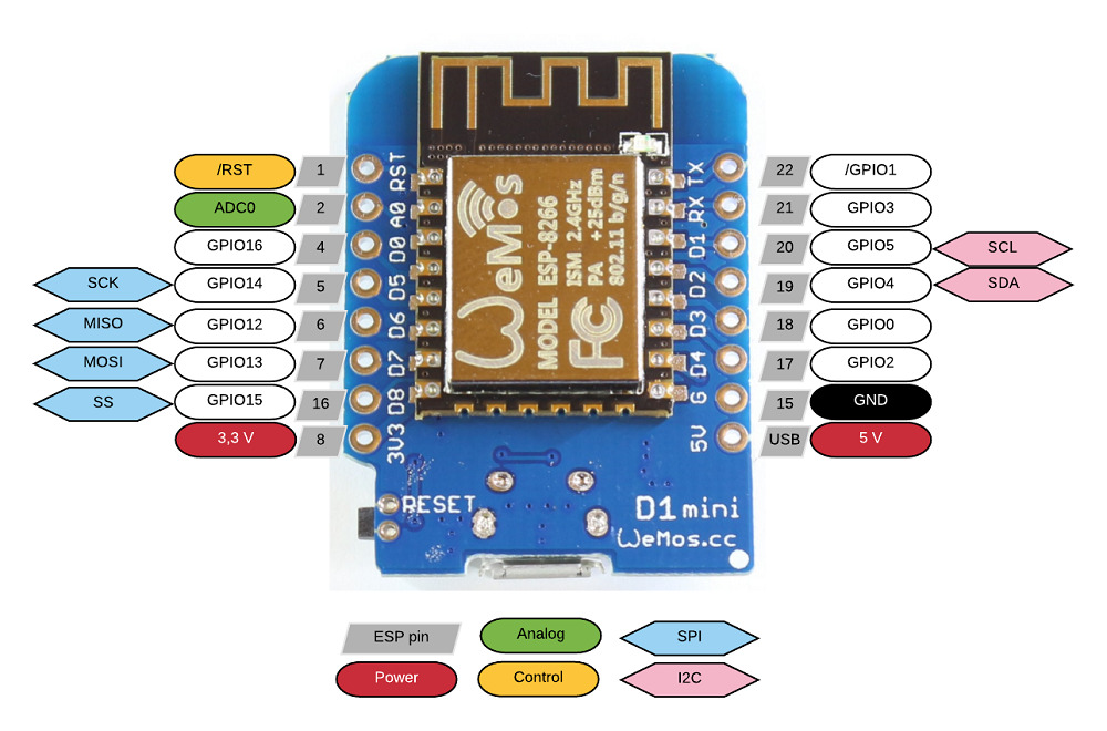
I got a bit confused by the I/O ports at first because there isn’t a one-to-one relationship between the printed numbers on the WeMos board and what goes into the Arduino sketch. I soon figured out that the sketch referrers to DPIO ports, which is not what is printed on the board. The image below shows the relation between the two.
Inputs
- D1/GPIO5 Temperature sensor
Outputs
- D2/GPIO4 Relay
- D3/GPIO0 Spare
- D4/GPIO2 Spare
Schematic drawing
Parts used
- 1 × Darlington-driver, 7 step, ULN2003A, DIL16, In: 2.7K/5V
- 1 × DIL socket, 16-pin, 7.62mm
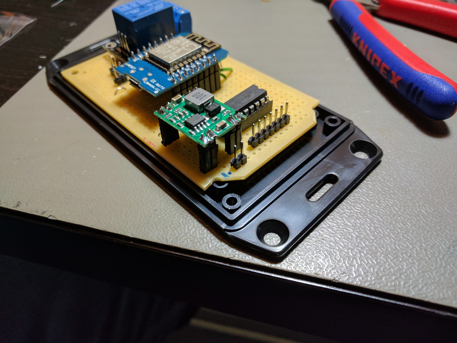
- 1 × Enclosure, plastic (1591 FL), 112x62x31mm, flange
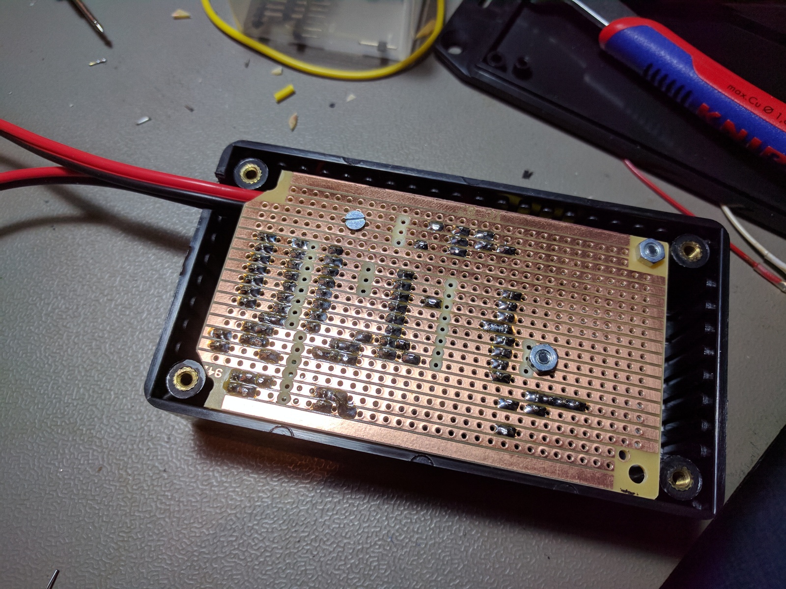
- 1 × PCB, stripboard prototyping, 94x53mm, 50cm2
- 1 × Power jack, w/wire, female, 2.1mm x 5.5mm
- 1 × Power jack, w/wire, male, 2.1mm x 5.5mm
- 1 × Relay module, 1 CO, w/driver, 5 VDC, 10A 250V
- 1 × Resistor, carbon film, 0.25W, 10 kΩ, 5%
- 2 × Spacer, round unthreaded, 3mm, Ø6mm, Delrin
- 31 × Straight pin header, female, Single row, 2.54mm
- 38 × Straight pin header, male, Single row, 2.54mm
- 1 × Temperature sensor DS18B20, -55 °C - 125 °C, 3V - 5.5V
- 1 × Voltage step-down buck converter, In: 7-28V, Out: 5V/3A
- 1 × WeMos D1 mini, WiFi dev. board, ESP8266
Last commit 2024-11-11, with message: Add lots of tags to posts.