
Keypad with programmable PIN code, two outputs (modes) and protection against repeated incorrect PINs. Uses an AVR ATtiny2313 microcontroller.
Table of contents
Details
This module uses an AVR microcontroller to interface a cheap numeric keypad. The PIN code is set by the user and stored in EEPROM. If entered correctly; a one second pulse is sent on either output 1 or 2, depending on the selected mode. A tamper pin will be shorted to 0V when the module is connected.
This keypad module is not itself meant to control anything, but it provides trigger signals for other control modules to act upon (like the Intruder alarm system controller). It has three LEDs (green, red and alarm) which can be used to convey messages from that other control module. Powered by: 5V.
Video
Quick demo of the module. Shows entering correct, and wrong PIN; and programming a new PIN.
Operation
Modes
Mode 1
To activate mode 1 enter PIN + * (star), a one second green light indicates correct PIN and confirms command.
Mode 2
To activate mode 2 enter PIN + # (number sign), a two seconds green light indicates correct PIN and confirms command.
PIN code
Change PIN
To change PIN enter current PIN + 0 (zero), a yellow light indicates that a new PIN can be entered. The new PIN is entered and confirmed with #, a green light indicates a successful change. Any button other than # will reject the new code and keep the old one, a red light indicates this.
Wrong PIN
When the wrong PIN is entered you get a red light. If the wrong PIN is entered three times the panel will not be usable for one minute. The red light will flash during this period.
I/O
Inputs
- PD2 Keypad R1
- PD3 Keypad R2
- PD4 Keypad R3
- PD5 Keypad R4
Outputs
- PB0 Keypad K1
- PB1 Keypad K2
- PB2 Keypad K3
- PB3 Mode 1 signal
- PB4 Mode 2 signal
- PB5 Green LED indicator
- PB6 Red LED indicator
- PB7 Life-signal (to Module stability monitoring unit 2)
D-Sub 9-pin
- 5V
- 0V
- Channel 1
- Channel 2
- Tamper N.C
- Life-signal (to Module stability monitoring unit 2)
- Alarm LED from Alarm unit
- Green LED from Alarm unit
- Red LED from Alarm unit
Keypad
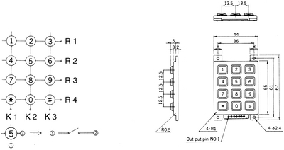
- n/a
- K3
- K2
- K1
- R1
- R2
- R3
- R4
Source code
- Bascom-AVR source is available in a git repository:
- https://github.com/thomasjsn/AVR-Programmable-keypad
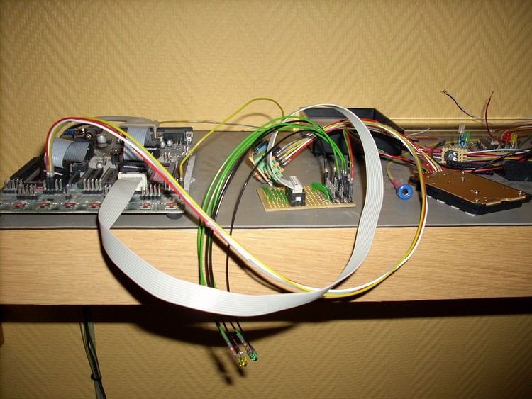
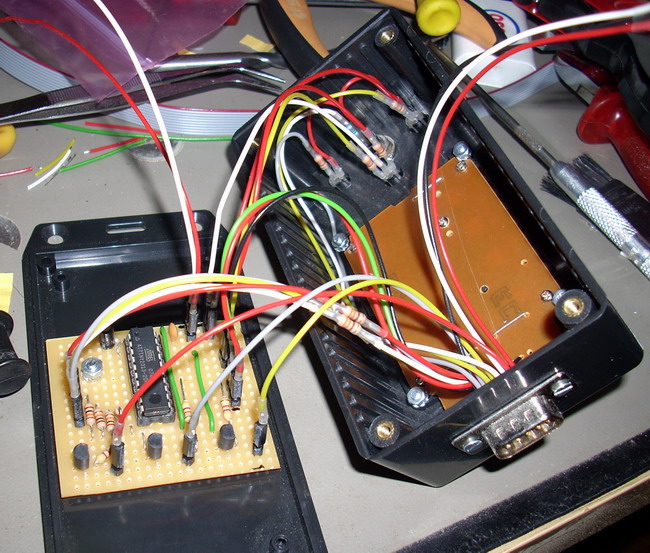
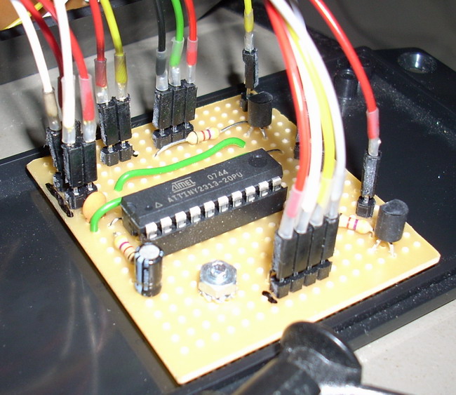
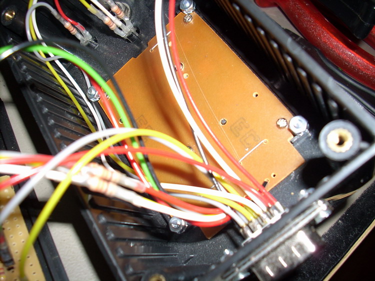
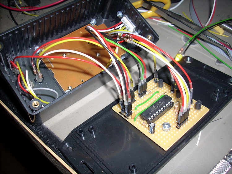
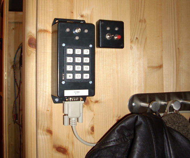
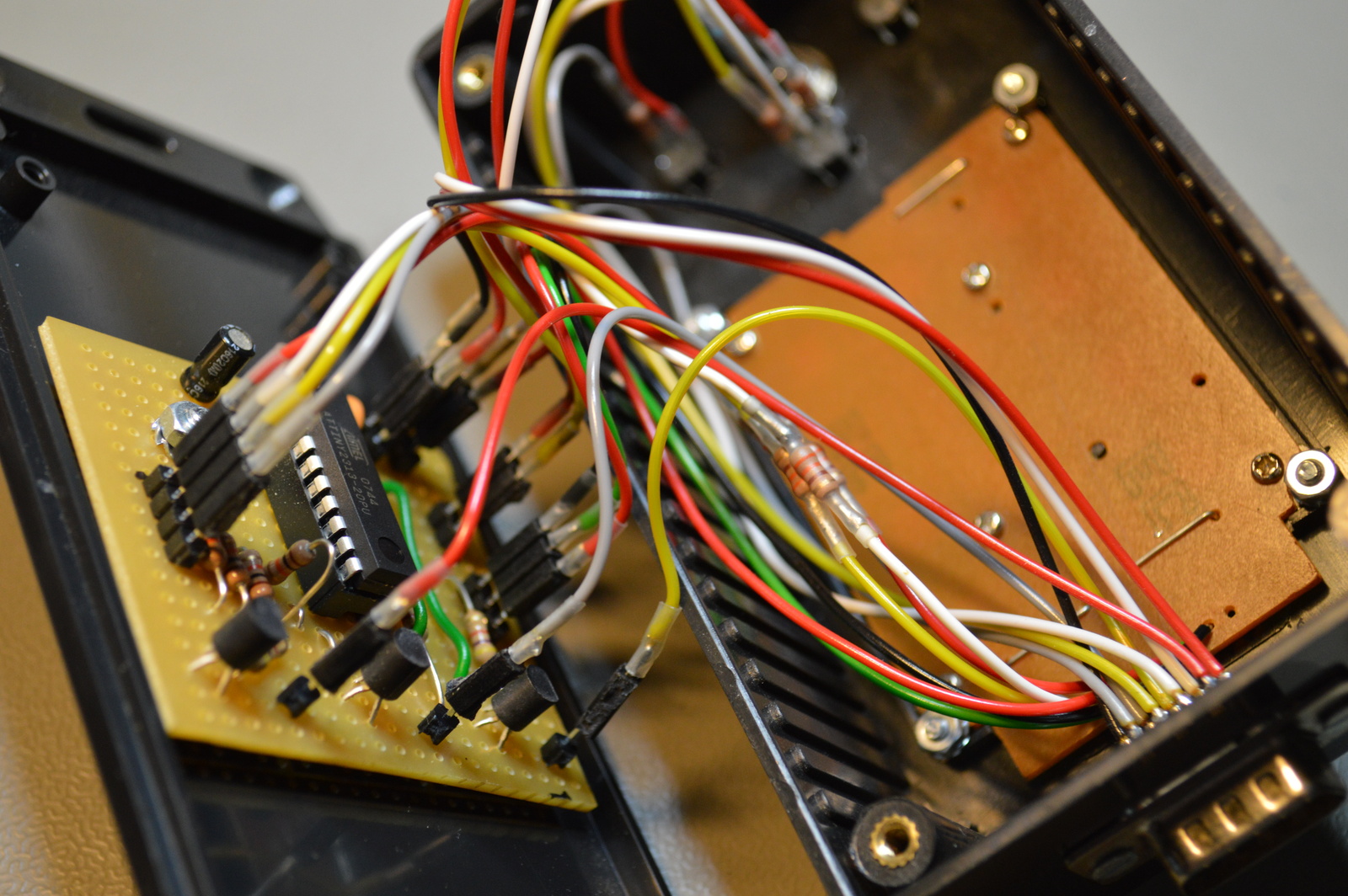
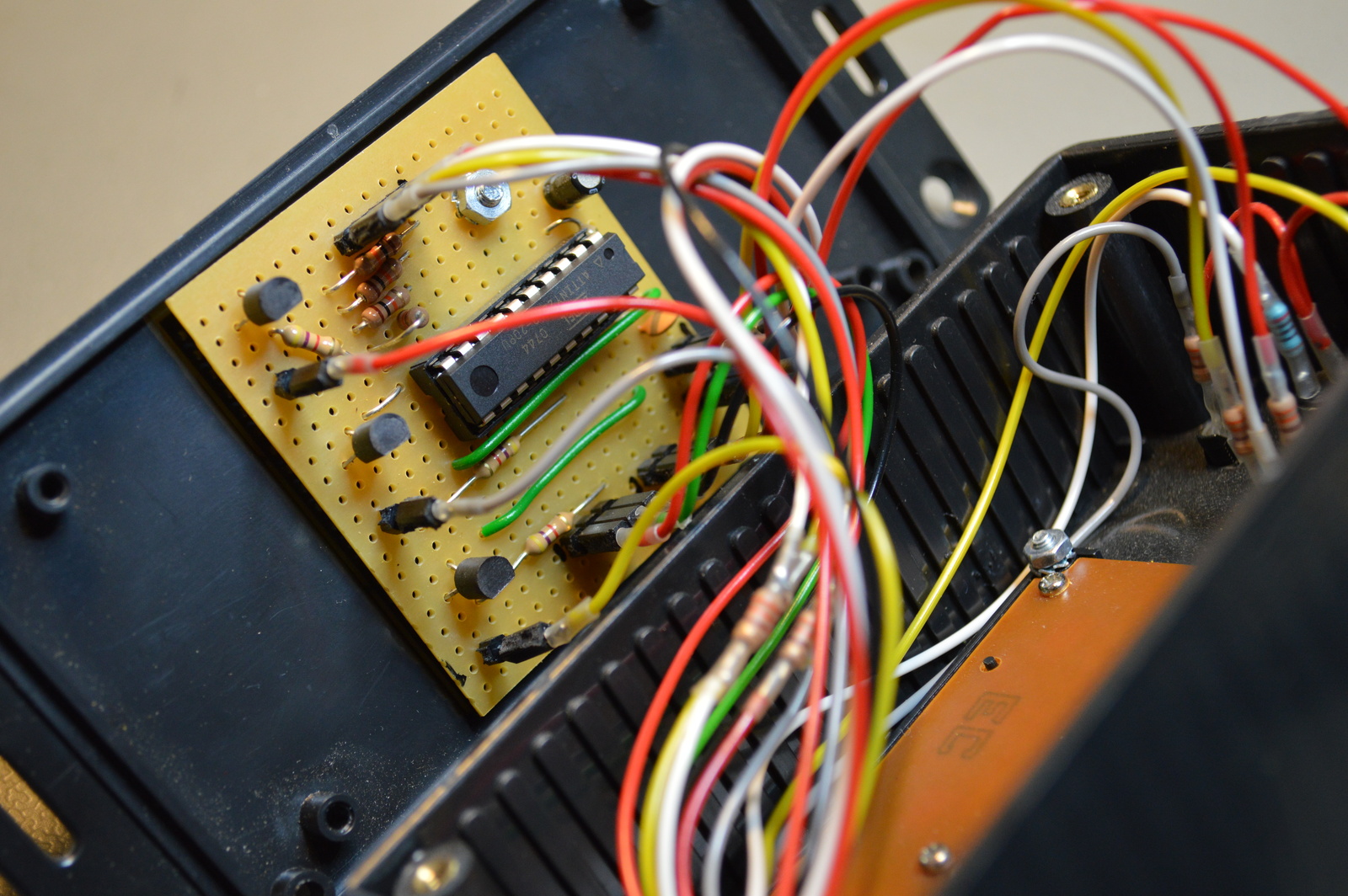
Photos
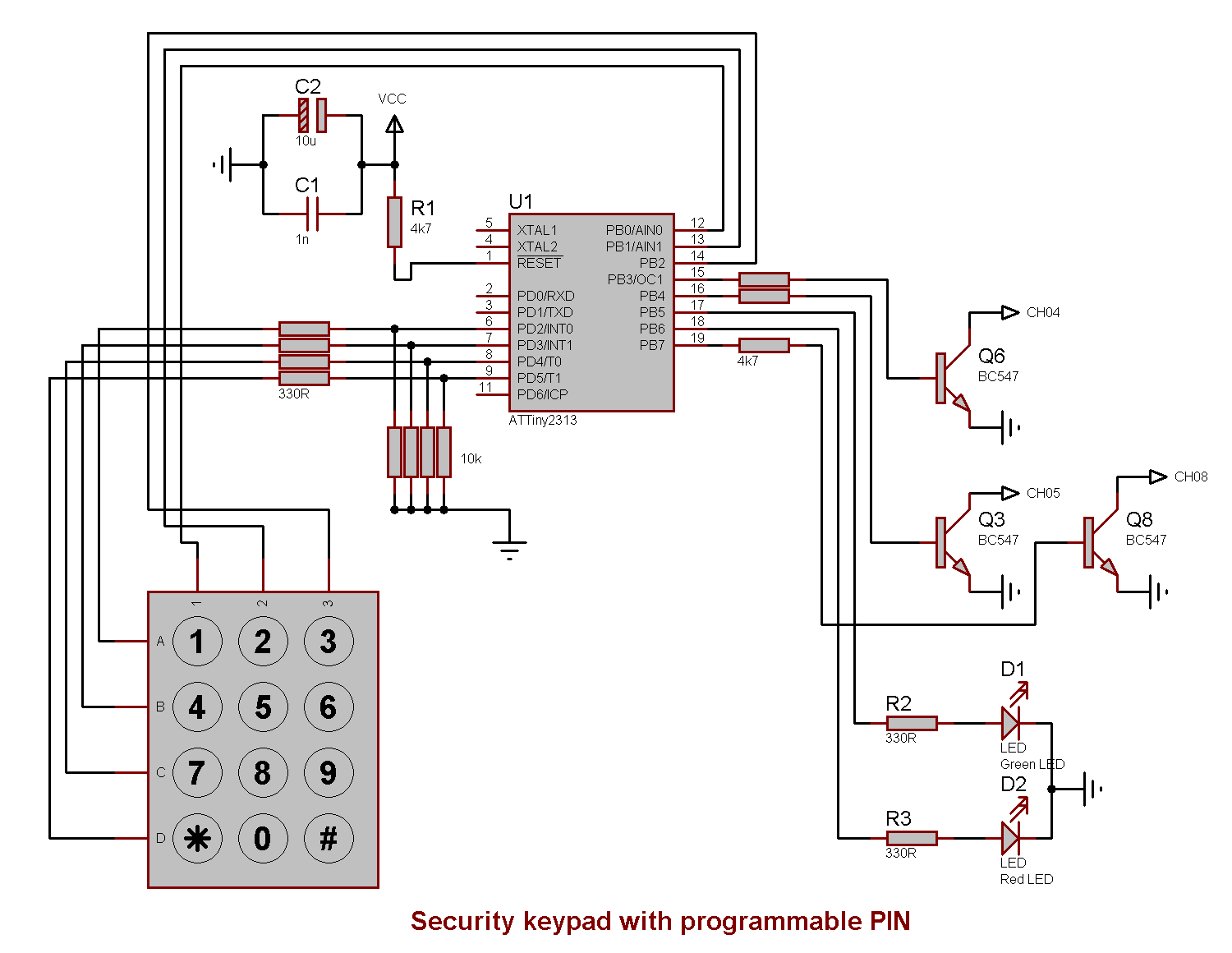
Schematic drawing
Parts list
- 1 × AVR ATtiny2313-20PU, DIL-20, 20 MHz, 18 I/Os
- 1 × Capacitor, aluminium electrolytic, 10 µF, 25V
- 1 × Capacitor, ceramic, 1 nF, 100V
- 1 m Control cable, 10-cores, 0.14mm2, 250 V, Ø 5.4mm
- 1 × D-sub soldering cups, 9 pin male
- 1 × DIL socket, 20-pin, 7.62mm
- 1 × Enclosure, plastic (1591 FL), 120x65x40mm, flange
- 1 × Fuse 5x20 mm, 400 mA, fast-acting
- 1 × Fuse holder, wire, 5x20 / 6.3x32mm
- 1 × Keypad, 12 buttons, 4x3, AK-804
- 1 × LED 5mm clear, Red, 2.0V, 20mA, 140mcd, 6°
- 3 × LED 5mm, Red/Green, 2.0 2.1V, 10mA, 100 63mcd, 30°
- 3 × LED holder 5mm, Black plastic
- 1 × LED holder 5mm, Chrome-plated plastic, reflector
- 32 cm2 PCB, stripboard, 100x160mm, 160cm2
- 8 × Resistor, carbon film, 0.25W, 330 Ω, 5%
- 4 × Resistor, carbon film, 0.25W, 4.7 kΩ, 5%
- 4 × Resistor, carbon film, 0.25W, 10 kΩ, 5%
- 1 × Resistor, metal film, 0.6W, 200 Ω, 1%
- 1 × Spacer, round unthreaded, 3mm, Ø6mm, Delrin
- 16 × Straight pin header, female, Single row, 2.54mm
- 16 × Straight pin header, male, Single row, 2.54mm
- 3 × Transistor, NPN, 100 mA, 45V, 0.5W, BC547B
Last commit 2024-11-11, with message: Add lots of tags to posts.