Two channel strobe light controller, using the AVR ATtiny2313 microcontroller. Five flashing patterns that can be selected manually or cycled through. PWM outputs.
Table of contents
Details
The warning lights controller has two PWM driven outputs, that each can handle a load of 3 amps. It has five sequences, and can be set on a single sequence or to cycle through. When selecting a sequence manually it is stored in EEPROM and continues on power-up. Much of the hardware and software is based on the Emergency strobe light with 33 LEDs project. Can be used to drive warning LEDs. Powered by: 9-24V.
Sequences
- Flashing with fade
- 3 × strobe, pause
- Delayed flash
- Random pause strobe
- Strobe
I/O
Inputs
- PD0 Select program
- PD1 Run all programs
Outputs
- PB3 Channel 1 (PWM)
- PB4 Channel 2 (PWM)
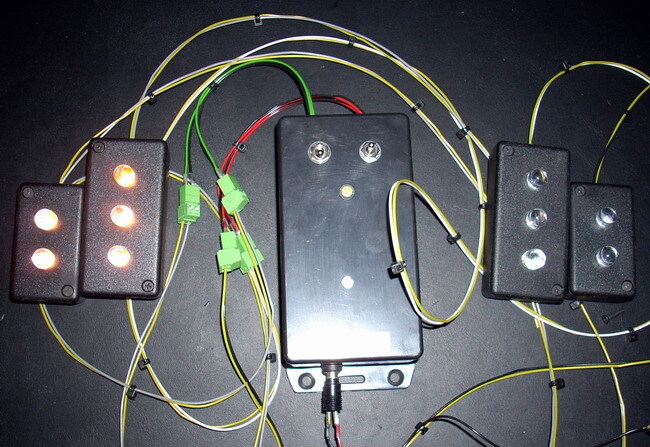
Warning LEDs
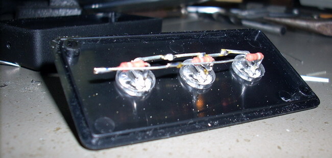
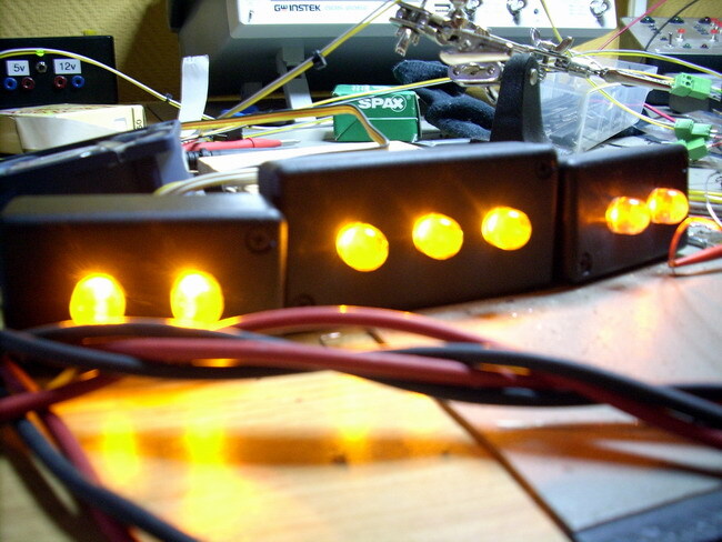
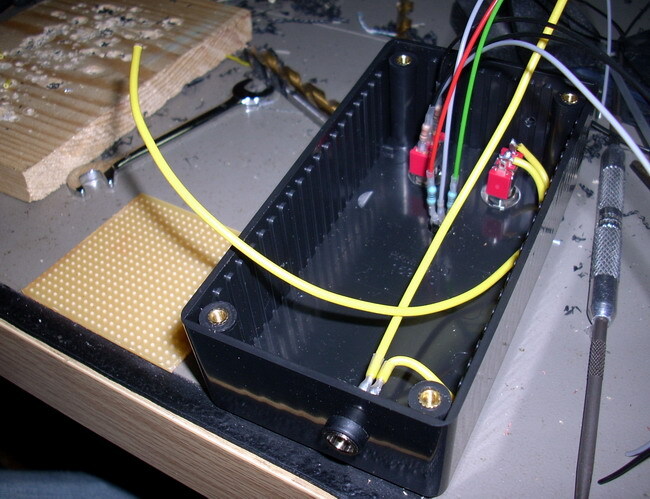
Four very simple LED warning lights, with a total of 10 LEDs; 2x2 and 2x3. The yellow LEDs have four chips, making them pretty bright. And with a 40 degree light beam they are quite visible, even more so at a distance. So they make pretty good warning lights. Powered by: 12-13.8V.
Parts I used to build the LED warning lights:
- 2 × Enclosure, plastic (1551), 60x35x20mm
- 2 × Enclosure, plastic (1551), 80x35x20mm
- 10 × LED 10mm clear, Yellow, 2.1V, 80mA, 8lm, 40°
- 10 × Resistor, metal film, 1W, 150 Ω, 5%
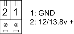
- 4 × Terminal block, pluggable, 3.5 mm, 2-pin screw female
- 1 m Wire, stranded, 0.22mm2, Black
- 4 m Wire, stranded, 0.22mm2, Grey
- 1 m Wire, stranded, 0.22mm2, White
- 4 m Wire, stranded, 0.22mm2, Yellow
Source code
- Bascom-AVR source is available in a git repository:
- https://github.com/thomasjsn/AVR-Warning-strobe-light-controller
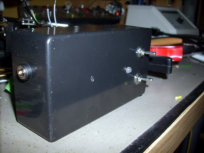
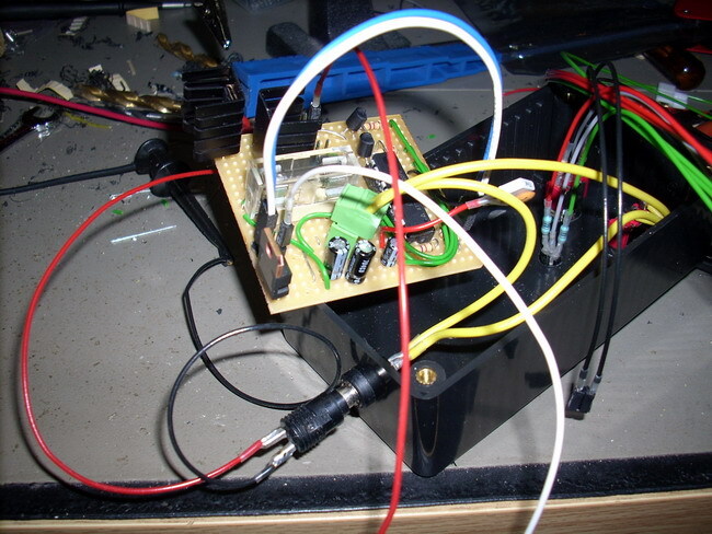
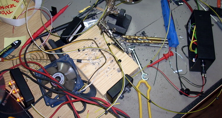
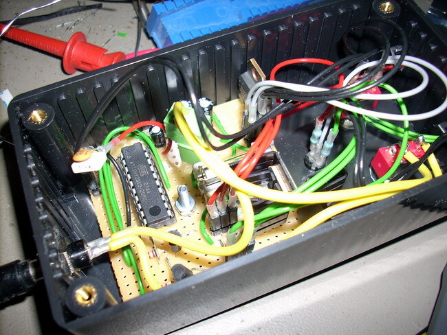
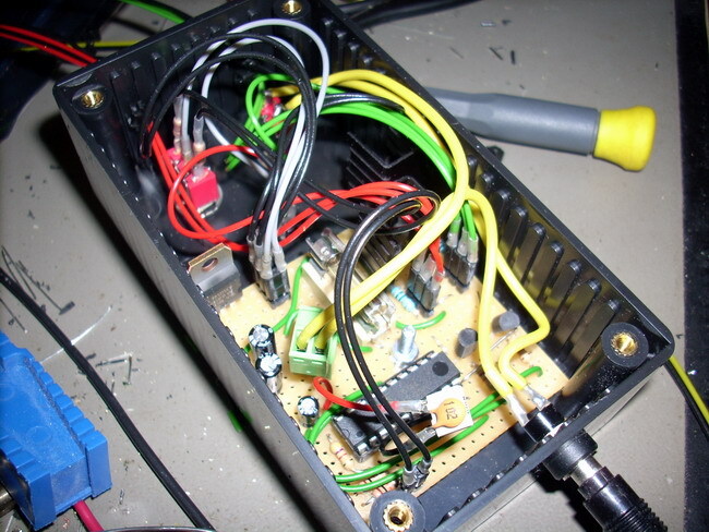
Photos
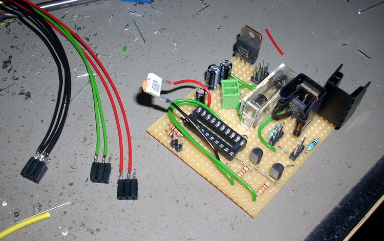
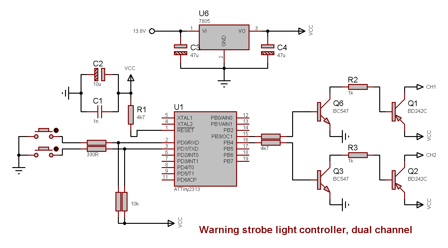
Schematic drawing
Parts list
- 1 × AVR ATtiny2313-20PU, DIL-20, 20 MHz, 18 I/Os
- 1 × Capacitor, aluminium electrolytic, 10 µF, 25V
- 2 × Capacitor, aluminium electrolytic, 47 µF, 25V
- 1 × Capacitor, ceramic, 1 nF, 100V
- 1 × Capacitor, metallized polyester foil, 10 nF, (0.01 µF)
- 1 × DIL socket, 20-pin, 7.62mm
- 1 × Enclosure, plastic (1591 FL), 120x65x40mm, flange
- 1 × Fuse 5x20 mm, 2 A, fast-acting
- 1 × Fuse holder, open, PCB, 5x20mm
- 2 × Heatsink, 27.3K/W, 19mm, attachable, TO220
- 1 × LED 5mm, Red/Green, 2.0 2.1V, 10mA, 100 63mcd, 30°
- 1 × LED holder 5mm, Black plastic
- 32 cm2 PCB, stripboard, 100x160mm, 160cm2
- 1 × Power jack, panel, 2.1mm, plastic housing
- 2 × Resistor, carbon film, 0.25W, 330 Ω, 5%
- 3 × Resistor, carbon film, 0.25W, 4.7 kΩ, 5%
- 2 × Resistor, carbon film, 0.25W, 10 kΩ, 5%
- 4 × Resistor, metal film, 0.6W, 1 kΩ, 1%
- 1 × Spacer, round unthreaded, 3mm, Ø6mm, Delrin
- 3 × Straight pin header, female, Dual row, 2.54mm
- 8 × Straight pin header, female, Single row, 2.54mm
- 3 × Straight pin header, male, Dual row, 2.54mm
- 8 × Straight pin header, male, Single row, 2.54mm
- 1 × Switch, toggle, 1-pole, micro, on-off-(on)
- 1 × Switch, toggle, 1-pole, micro, on-on
- 1 × Terminal block, pluggable, 3.5 mm, 2-pin screw female
- 5 × Terminal block, pluggable, 3.5 mm, 2-pin vertical male
- 2 × Transistor, NPN, 100 mA, 45V, 0.5W, BC547B
- 2 × Transistor, PNP, 3 A, 100V, 40W, BD242C
- 1 × Voltage regulator +5V, 2 A, L78S05CV
Last commit 2024-11-11, with message: Add lots of tags to posts.