As the weather is warming up here in Norway — my kids have gotten their bikes out. To make it more fun, both for them and me, I figured I’d build a series of traffic signals that they could play with.
I first started with a traffic light, simple — red, yellow and green. To control it I am using a Raspberry Pi Zero W, this will allow me to make it communicate on Wi-Fi and MQTT later.
Table of contents
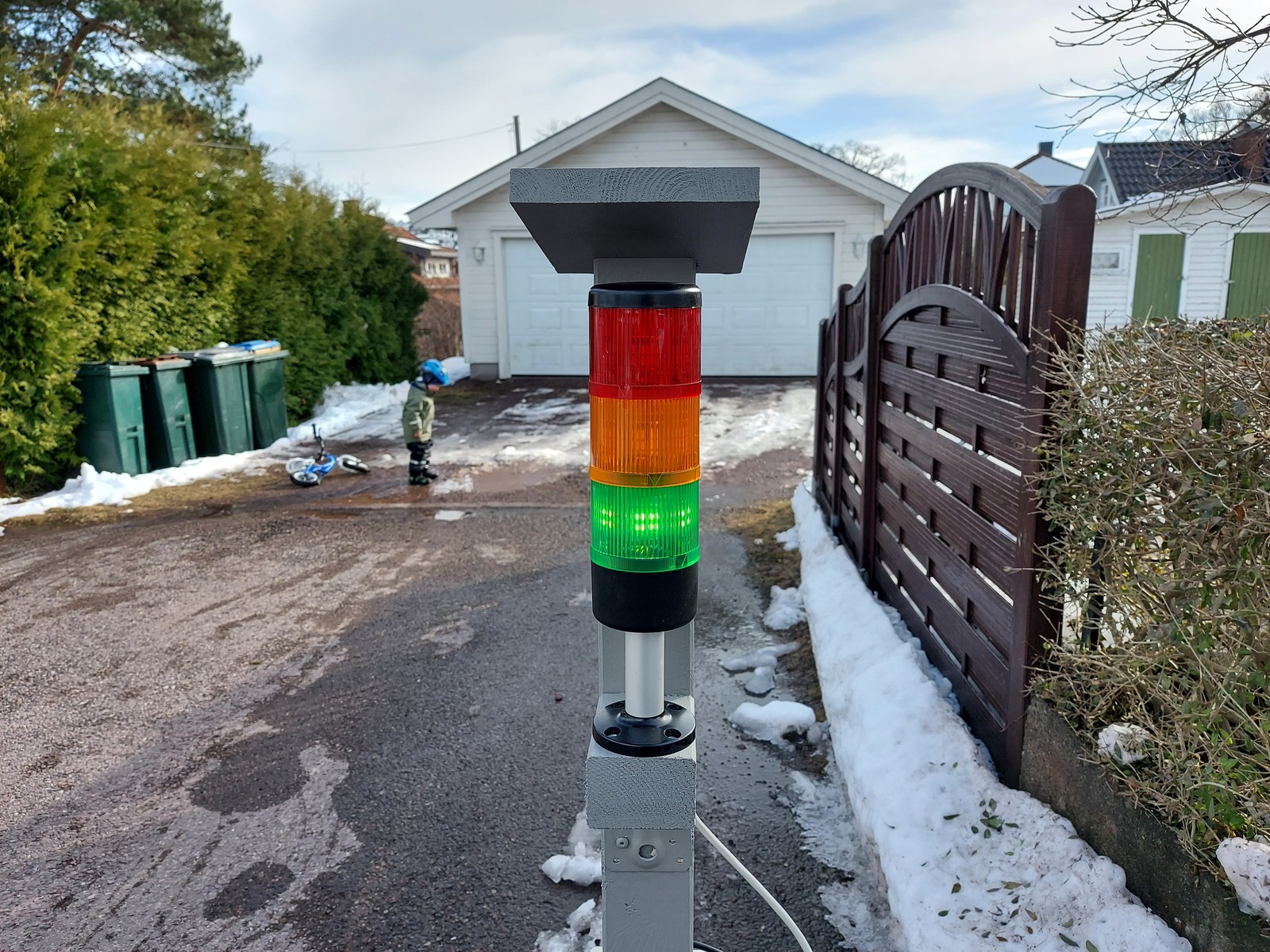
In action
The stand
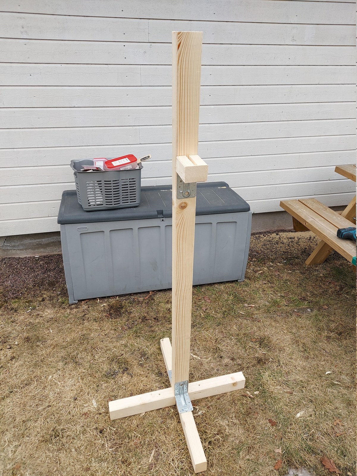
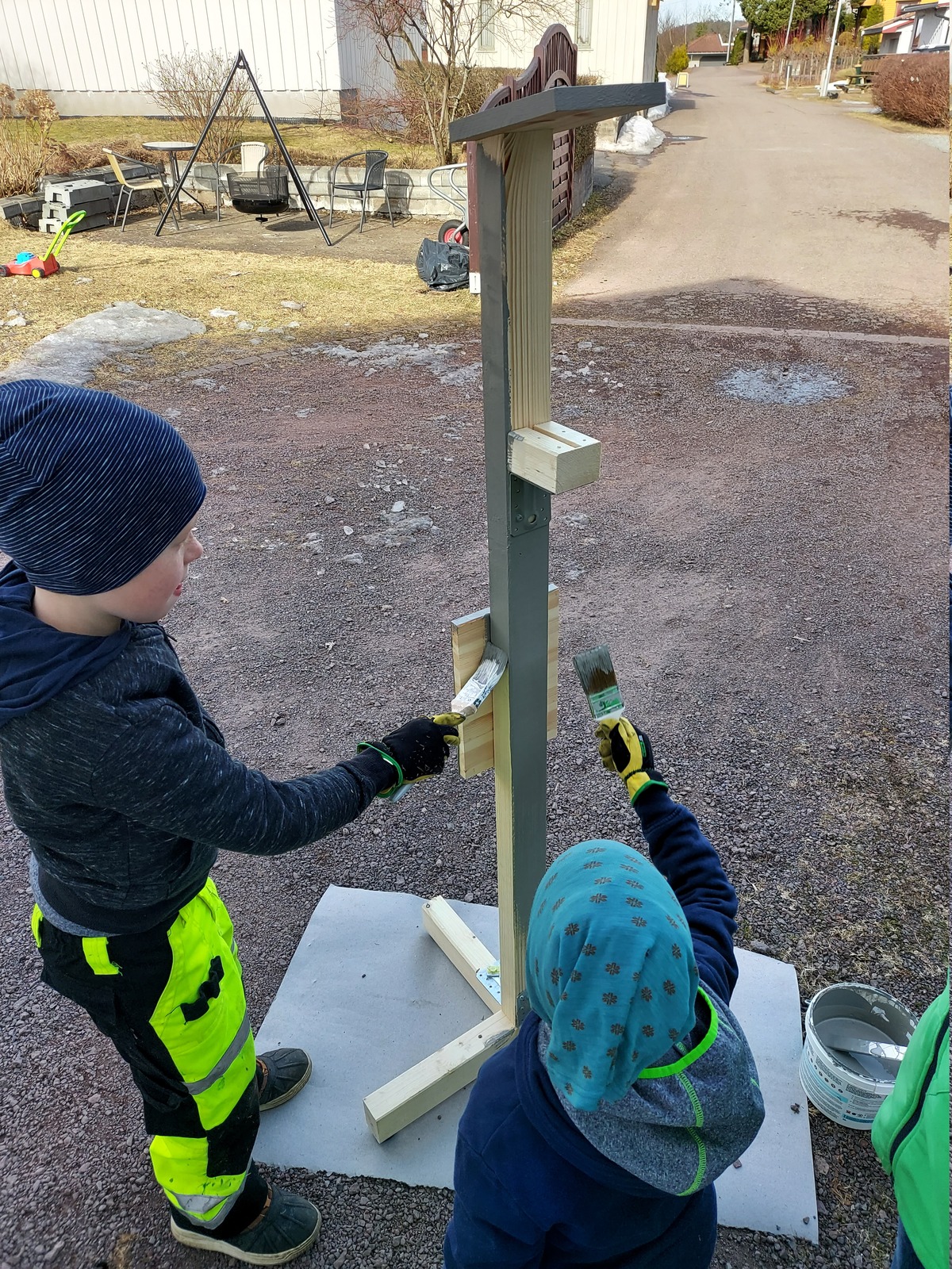
The stand is very basic, it’s just a 2×3" pole with a foot — also made by 2×3". I mounted a small block of wood for the stack lights, and cut a groove to route the wires through.
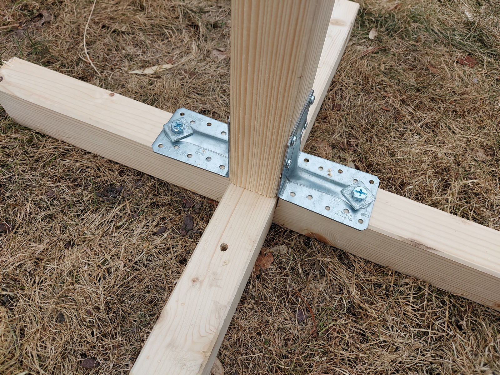
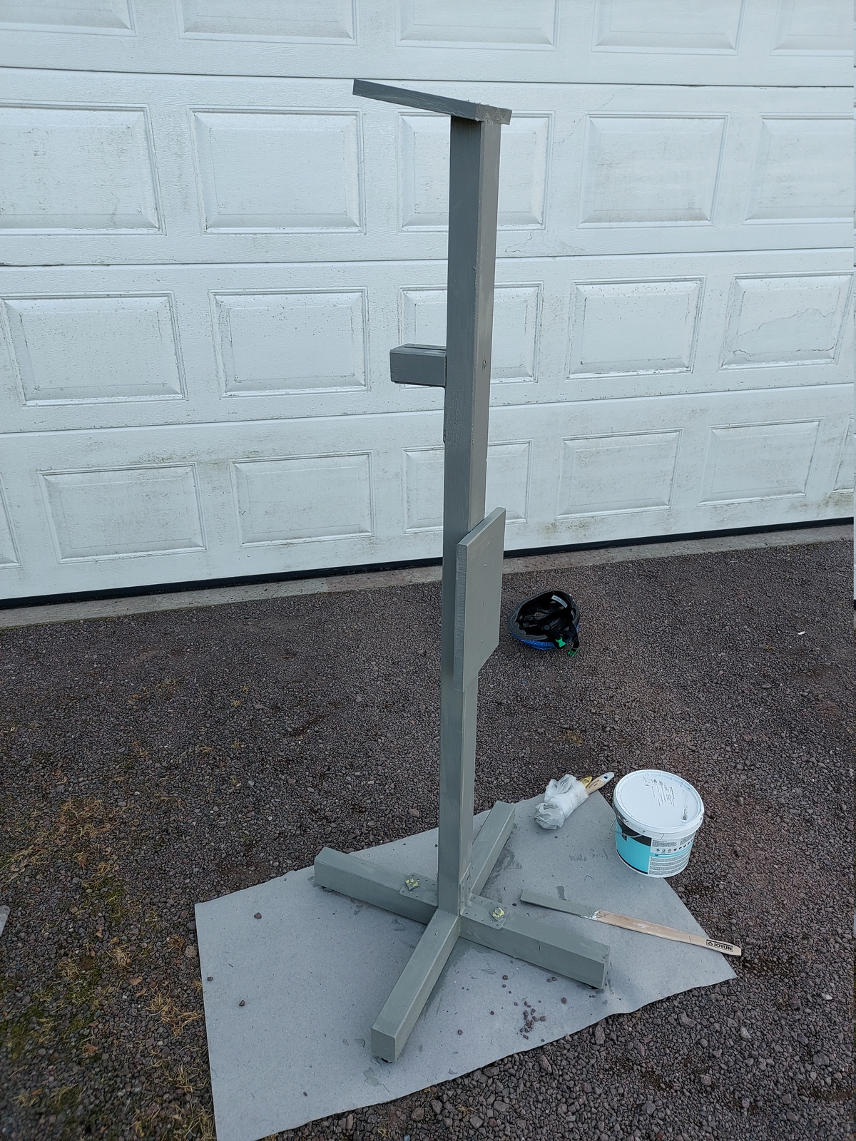
I made cut-outs in the lumber for the foot, so they could be placed to form a cross. The pole is secured with angle brackets, and two bolts to the foot. It can be disassembled simply by removing those two bolts, to take up less space when stored in the winter.
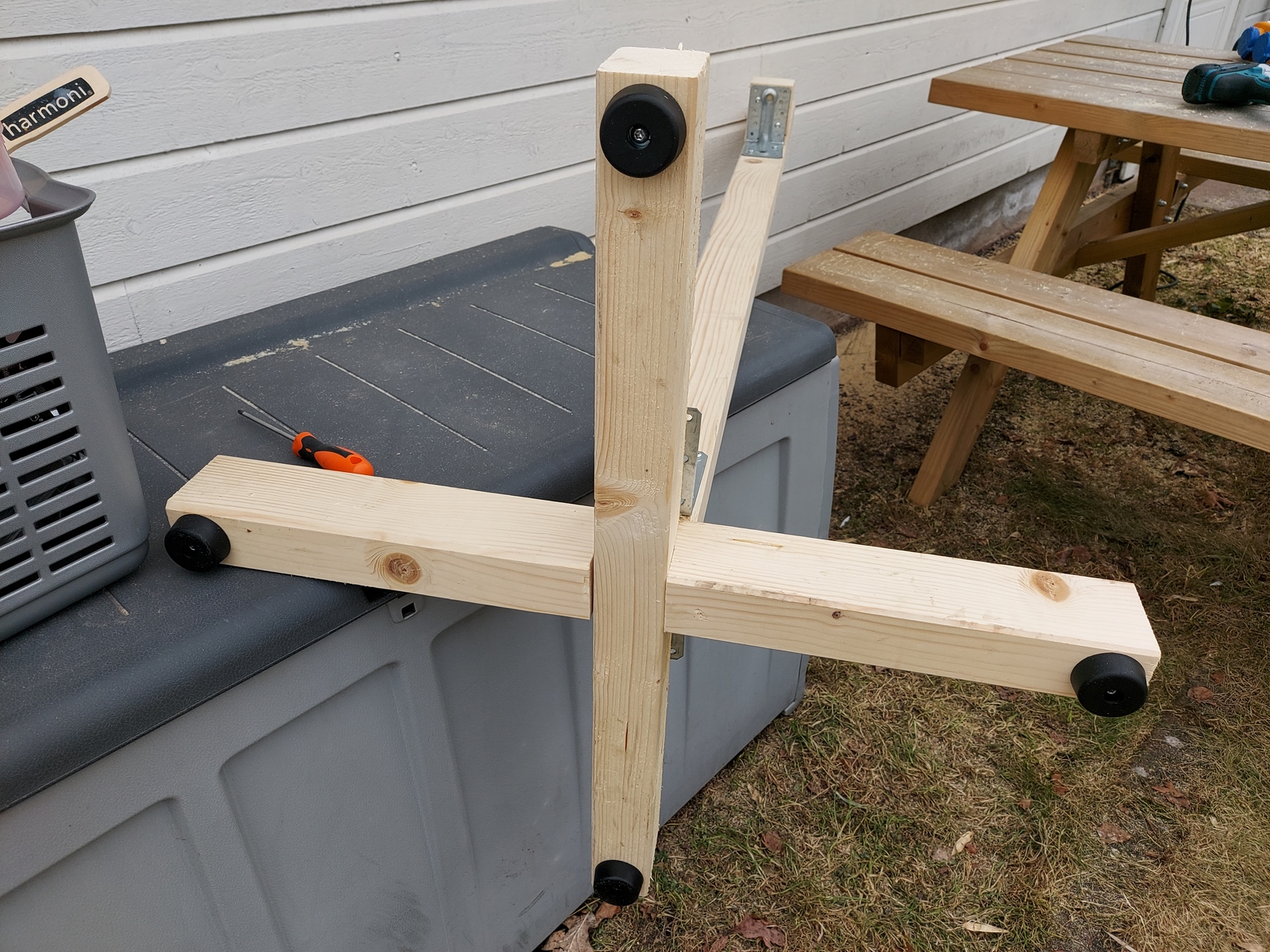
I attached four rubber feet to make it less wobbly.
On top I mounted a board at a slight angle — it just made it look nicer 😃 So this is what is looks like, before painting.

The next day I also mounted a board on the backside, to have somewhere to attach the box for the electronics.
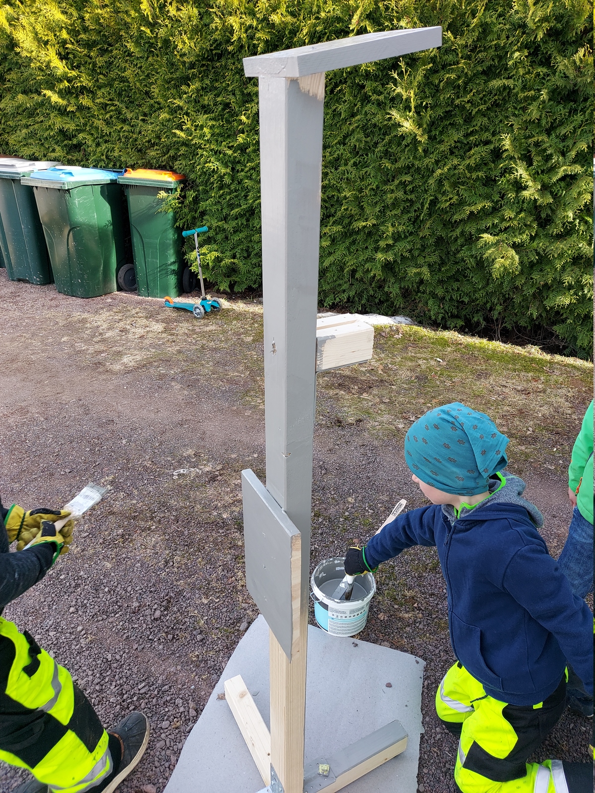
Painting
I originally intended for it to be black, but I couldn’t find the black paint. And we had some grey left over, and I didn’t want to go to the store. So the kids painted it grey 😃
Painting done, now ready for the electronics.
Raspberry Pi
I decided to go with a Raspberry Pi Zero W. Having the controller on Wi-Fi gives me a lot of options for future expansions. Like adding MQTT and communicating with other traffic signals.
And being able to SSH in makes it very easy to make adjustments to the software.
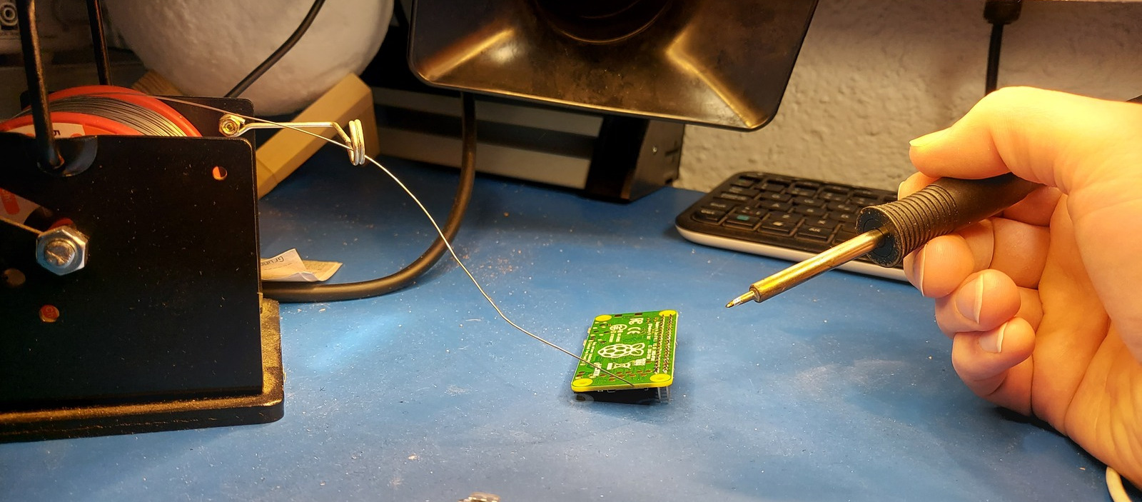
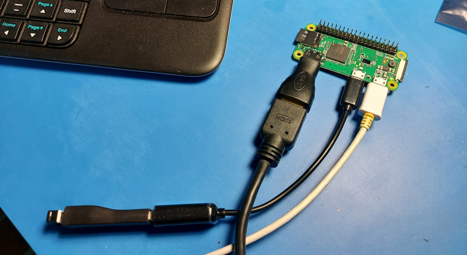
I first soldered on the headers for GPIO pins, flashed the SD card, and got the Raspberry Pi connected to the Wi-Fi. I’ve written an article about getting the Pi ready, but here is a quick run-down:
Wipe and flash the SD card:
$ sudo wipefs -a /dev/sdd
/dev/sdd: 2 bytes were erased at offset 0x000001fe (dos): 55 aa
/dev/sdd: calling ioctl to re-read partition table: Success

$ sudo dd bs=4M if=2021-01-11-raspios-buster-armhf-lite.img of=/dev/sdd status=progress conv=fsync
1862270976 bytes (1.9 GB, 1.7 GiB) copied, 317.779 s, 5.9 MB/s

$ lsblk
NAME   MAJ:MIN RM   SIZE RO TYPE MOUNTPOINT
sdd      8:48   1   3.7G  0 disk
├─sdd1   8:49   1   256M  0 part
└─sdd2   8:50   1   1.5G  0 part
Time to connect a monitor, keyboard, and power; and configure the Raspberry Pi OS.
Using the raspi-config application we can configure:
- Wi-Fi
- Hostname
- Enable SSH
- Timezone
It’s important to either change the password for the pi user, or delete it entirely. I always delete the pi user and make my own.
If you delete the pi user, you no longer need this file: /etc/sudoers.d/010_pi-nopasswd
Update and upgrade packages;
$ sudo apt update && sudo apt upgrade
$ sudo apt auto-remove && sudo apt clean
This took a long time! 🥱
Lastly — we need a python package to control the GPIO ports, and put our user in the gpio group:
$ sudo apt-get install python3 python3-rpi.gpio
$ sudo adduser thomas gpio
The HAT
Since I’m no longer using my Alertmanager stack lights, I reused that HAT (Hardware Attached on Top). It has five Darlington transistors and a Darlington driver. I only need three outputs now, but having a few extra is always nice 😃
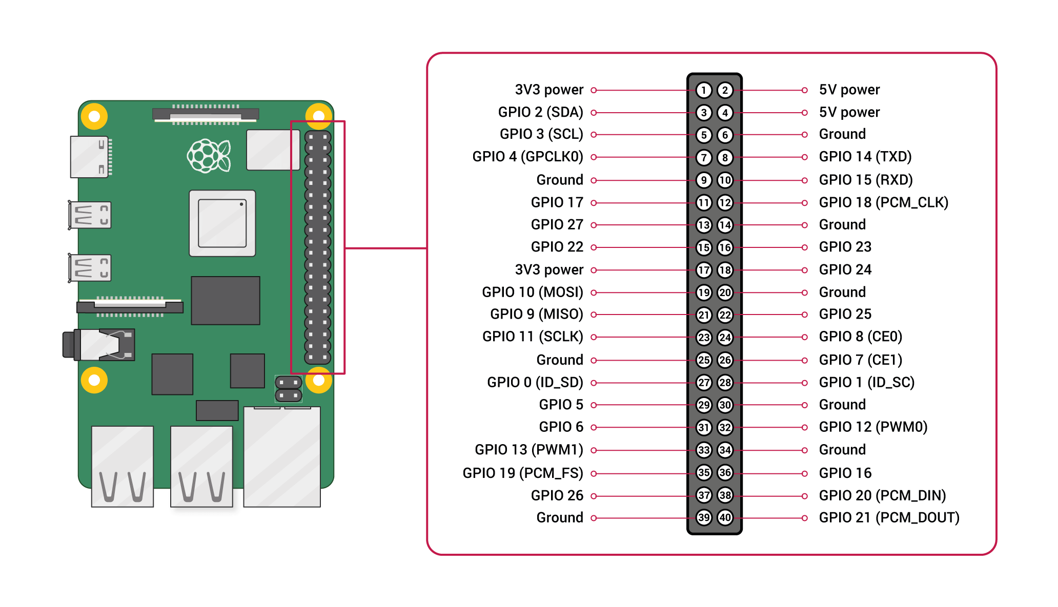
Outputs
- GPIO 24: Red
- GPIO 4: Orange
- GPIO 3: Green
- GPIO 2: Aux 1
- GPIO 17: Aux 2
Schematic diagram
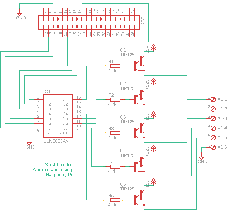
Parts used (HAT)
- 1 × Darlington-driver, 7 step, ULN2003A, DIL16, In: 2.7K/5V
- 5 × Darlington-transistor, PNP, 5 A, 60V, TIP125, TO-220
- 1 × DIL socket, 16-pin, 7.62mm
- 1 × PCB, perfboard prototyping, 50x70mm, 35cm2
- 5 × Resistor, carbon film, 0.25W, 4.7 kΩ, 5%
- 10 × Straight pin header, female, Dual row, 2.54mm
- 1 × Terminal block, pluggable, 5 mm, 6-pin vertical male
- 1 × Terminal blocks, screw, PCB, 3.5mm, 2-pin, straight
Putting it together

To make it portable I wanted to run the entire thing on a 12V battery. To power the Raspberry Pi 5V is needed as well, for that I used a step-down converter that I just put in a heat-shrink tube.
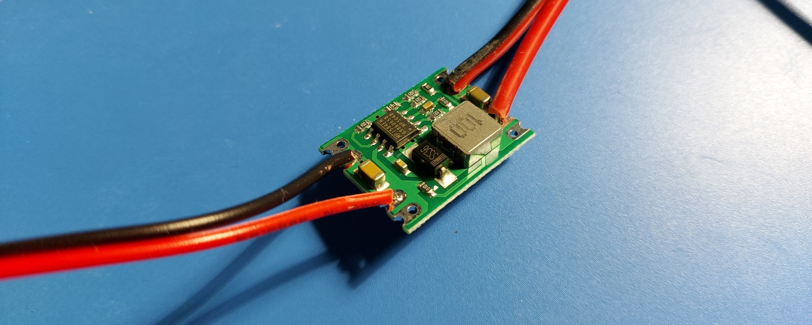
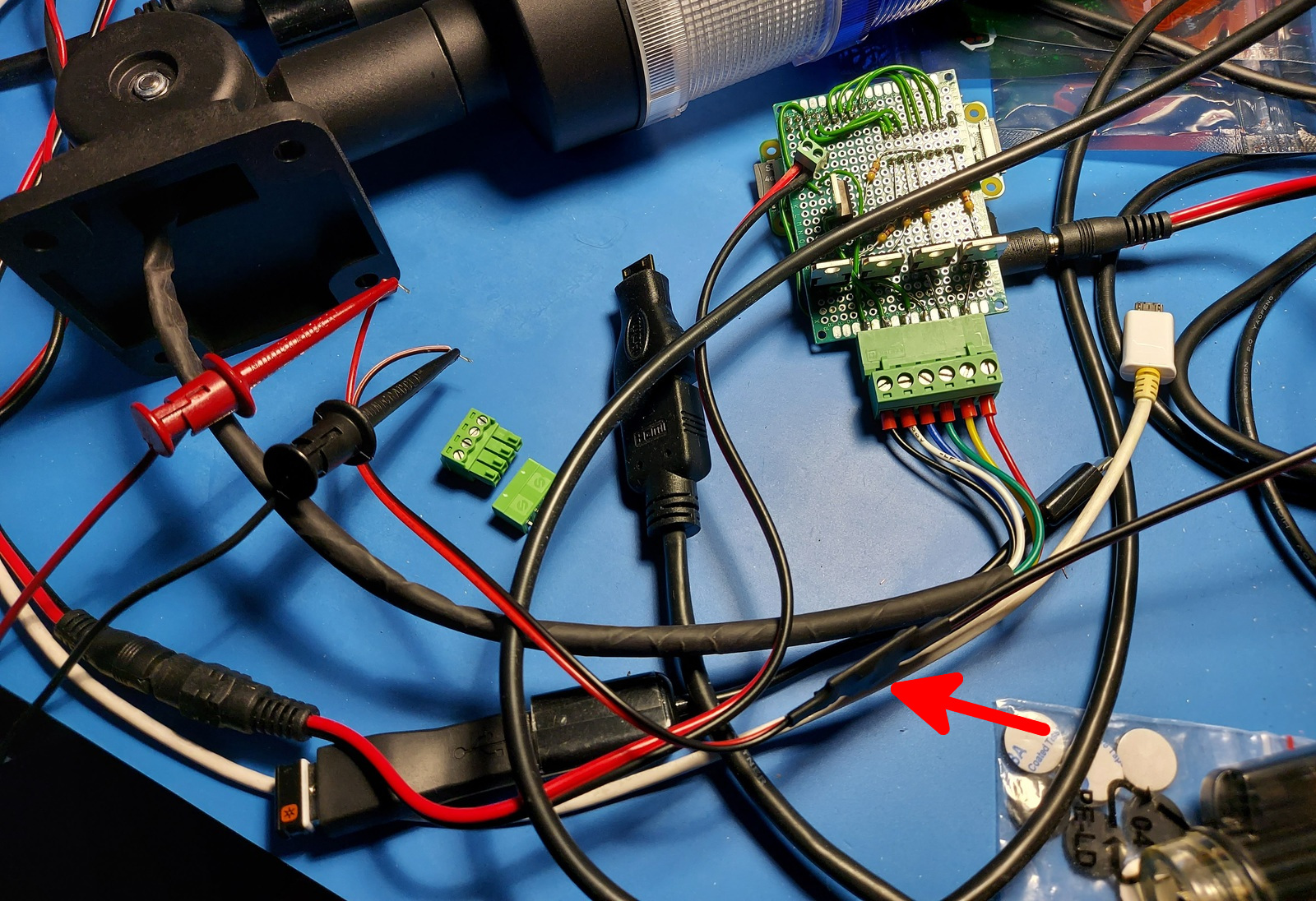
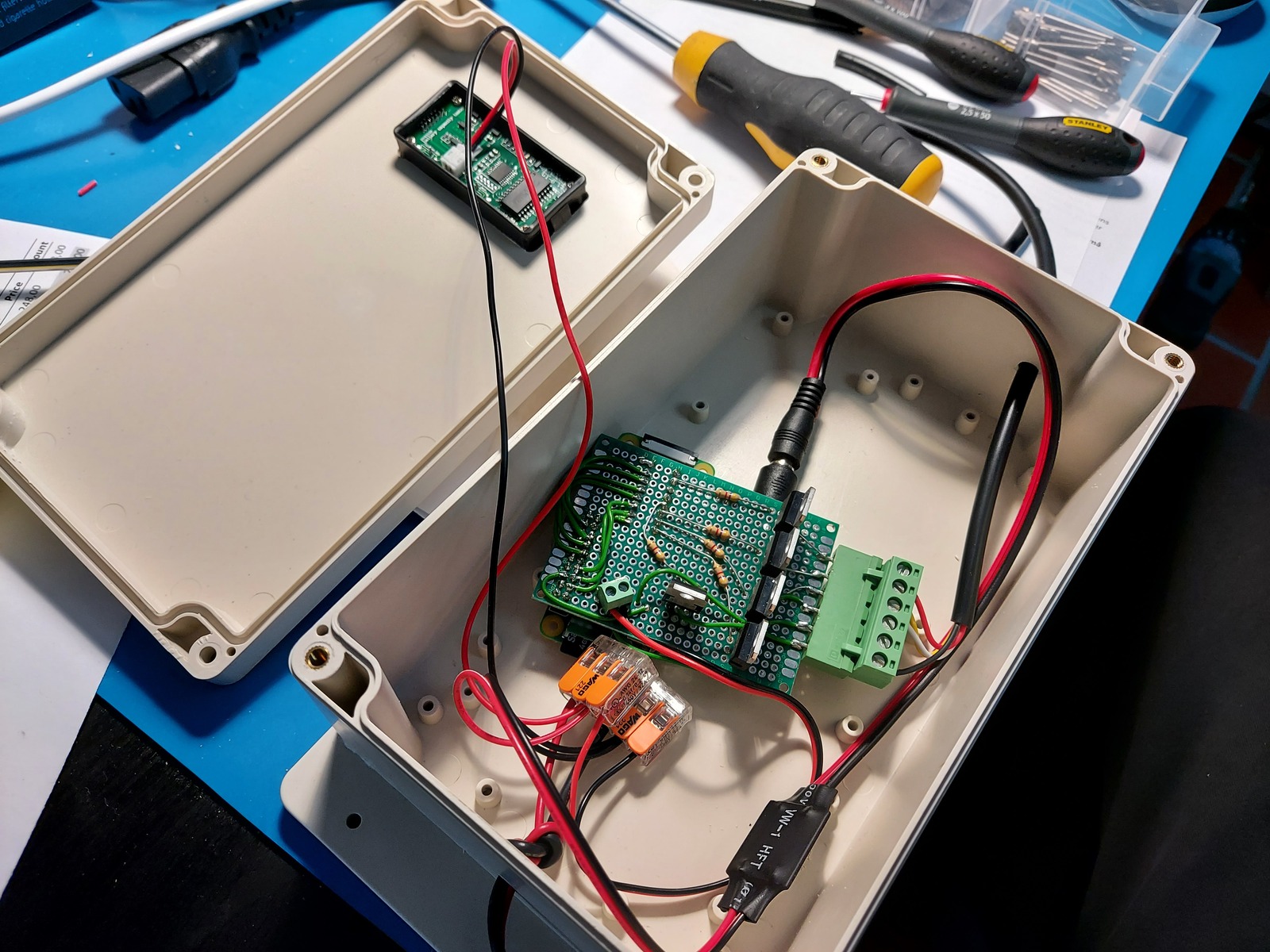
I also added a battery capacity indicator, to get an idea of the state of the battery.
Inside the enclosure with everything wired up.
Software
I started off very easy with the software, it just changes between red and green — with the proper timing on the yellow light in between. I already did a bit of research on the standard set by the Norwegian Public Roads Administration in another project.
Sequence and timing
- Cold start
- 5 seconds yellow flash
- 5 seconds yellow solid
- 5 seconds red
- Main loop
- 1 second red/yellow
- 5 seconds green
- 3 seconds yellow
- 15 seconds red
- Repeat main loop
I made the red light quite long, because it seems that the kids though it was fun to wait for the light to turn green 😛
- Source code is available in a git repository:
- https://github.com/thomasjsn/rpi-traffic-signals
Future plans
- Remote control
- Communicate with other traffic signals
- Input sensors
Parts used
- 1 × Battery capacity indicator, 12V-48V, acid lead/lithium
- 1 × Battery, lead-acid rechargeable 12V, 7.2Ah, 151x95x65, 2.7kg
- 0.2 m Control cable, 4-cores, flexible, 0.5mm2, 20AWG
- 1 × Enclosure, plastic (waterproof), 200x120x75mm, flange
- 3 × LED bulb BA15D, 12V White, 27 SMD, 450LM
- 1 × microSDHC card, Sandisk, 4GB, class 4
- 1 × Power jack adapter, USB micro, right angle, 2.1mm x 5.5mm
- 1 × Power jack, w/wire, male, 2.1mm x 5.5mm
- 1 × Raspberry Pi Zero W, 1.0GHz, 512MB RAM, BT, WLAN
- 1 × Stacklight, light signal, Red/Yellow/Green, Ba15d bulb
- 20 × Straight pin header, male, Dual row, 2.54mm
- 1 × Terminal block, pluggable, 3.5 mm, 4-pin screw female
- 1 × Terminal block, pluggable, 3.5 mm, 4-pin vertical male
- 1 × Terminal block, pluggable, 5 mm, 6-pin screw female
- 1 × Voltage step-down buck converter, In: 7-28V, Out: 5V/3A
- 2 × Wago splicing connector, 221-413, 3-conductor, 0.14-4 mm2
- 0.1 m Wire, stranded, 2-cores, 0.33mm2 (22 AWG), Red/Black
- 1.5 m Wire, stranded, 2-cores, 0.75 mm2, Red/Black
- 0.1 m Wire, stranded, 2-cores, PVC, 0.33mm2 (22 AWG), Red/Black
Last commit 2024-11-11, with message: Add lots of tags to posts.